Compatible with MaxxECU STREET/V1/RACE/PRO
VANOS head
This harness is built based on the non VANOS head, which means the VANOS heads CAM/HOME sensor connection is of another type and wont work.
There is two options to solve the problem if you have a VANOS head:
1.Change the CAM sensor to BMW 12141726590.
2.Cut the CAM connector in the harness, and replace with a connector that fits and also add switched +12V power supply to the sensor according to the below pinout.
Pin |
VANOS CAM sensor pinout |
Non-VANOS CAM sensor pinout |
1 |
+12V |
Signal |
2 |
Signal |
Sensor GND |
3 |
Sensor GND |
Shield |
Note: if you have a non VANOS head, you don't have to rewire or change the sensor.
Harness support
Terminated engine harness |
MaxxECU I/O |
Note |
+12V to injectors, ignition and solenoids |
Yes |
|
Cylinder head GND |
Yes |
|
OEM generator |
Yes |
|
OEM engine starter |
Yes |
|
Injectors (Bosch JPT connectors) |
INJ |
|
Ignition (VAG 1.8T coil-on-plug) |
IGN |
|
OEM intake temperature sensor |
IAT |
|
OEM coolant temperature sensor |
CLT |
|
OEM throttle position sensor |
TPS |
|
OEM idle valve solenoid |
GPO 4, 5 |
Not available on MaxxECU STREET |
OEM crank trigger |
TRIGGER |
|
OEM CAM trigger |
HOME |
|
VANOS solenoid |
GPO 3 |
|
Boost solenoid |
GPO 1 |
(no solenoid included) |
Fuel pump control |
GPO 2/or use any available output |
|
Engine FAN control |
GPO 6/or use any available output |
Not available on MaxxECU STREET |
Wideband LSU connector |
Yes |
LSU 4.2 |
MAP sensor hose in harness |
Yes |
Length
Start |
End |
Total length |
MaxxECU CMC connector |
Firewall entry/bushing |
850mm |
MaxxECU CMC connector |
LSU connector |
1600mm |
MaxxECU CMC connector |
IGN 1 coil connector |
1950mm |
Harness connectors
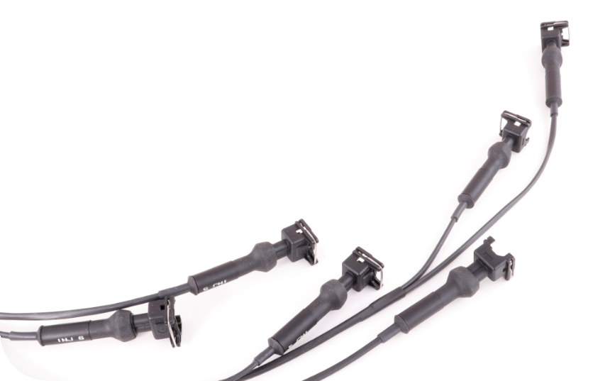
Injectors - Bosch JPT 2-way
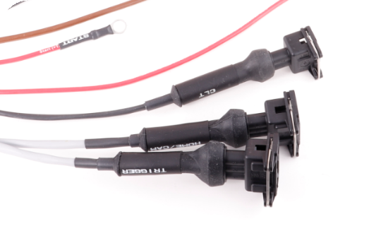
Trigger/HOME - Bosch JPT 3-way
CLT - Bosch JPT 2-way

IDLE solenoid = Bosch JPT 3-way
VANOS solenoid - Bosch JPT 2-way
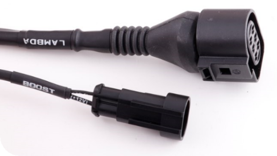
Lambda - Bosch LSU 4.2 6-way
Boost - Superseal 2-way
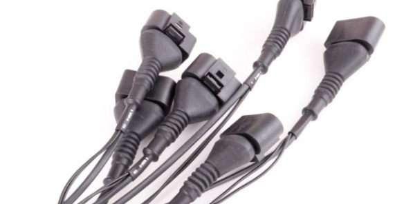
Ignition coils - VAG 4-way (COP)
Ignition coils ground <-- DO NOT FORGET TO MOUNT IN CYLINDER HEAD
Installation
The installation of the terminated engine harness is pretty straight-forward.
1.Mount all engine connectors, alternator and starter, do not forget Engine GND.
2.Place VAG coils (not included) and connect to harness. wired for LONG coils!!!!
3.Drill a 54mm hole in the firewall for harness bushing.
4.Route harness thru firewall and mount MaxxECU. Mounting position is very dependent on engine placement and vehicle model.
5.Connect +12V with external relay (fused with 20A) to the extra 12-pin connector, pin 7 (G).
6.Connect +12V with external relay (fused with 20A) to the extra 12-pin connector, pin 1 (A).
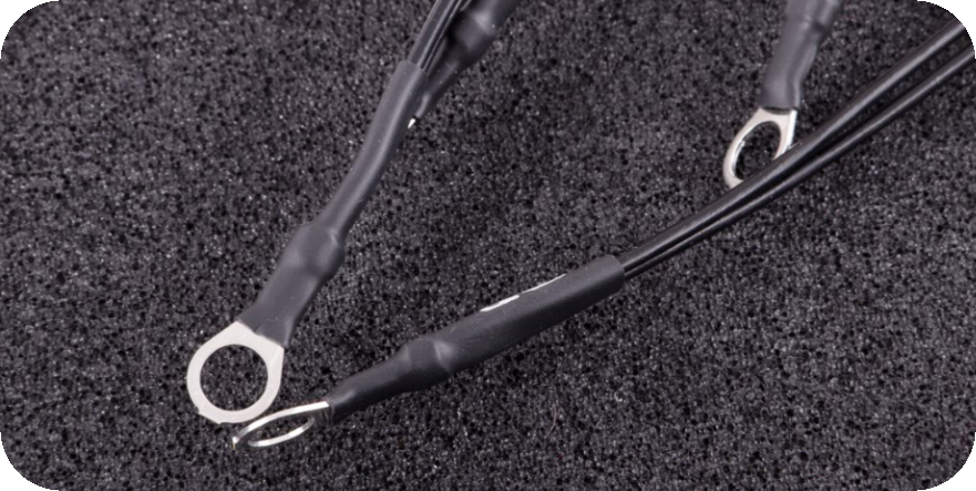
7.Connect engine ground (brown wire) on cylinder head.
8.Connect alternator (pin 12 (M) on 12-pin connector) to +12V ignition (in serial with a charge bulb).
9.Connect starter trigger (pin 6 (F) on 12-pin connector) to start button (+12V).
10.Wire fuel pump, fan, ecu power, ground, alternator and engine starter to 12-pin connector.
11.Wire extra connections like wheel speeds, ethanol sensor etc to 16-pin connector.
12-pin connector (seen from the wire side)
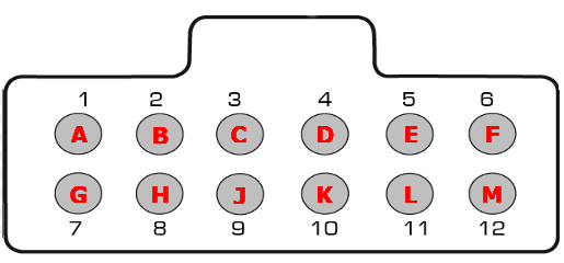
Note: Pinout is from the wiring side of the extra connector, not the terminated harness.
Pin |
Description |
1 (A) |
+12V ignition coils power supply |
2 (B) |
Engine ground |
3 (C) |
GPO 2 (fuel pump) |
4 (D) |
GPO 6 (FAN) |
5 (E) |
|
6 (F) |
Engine starter (+12V) - Connect to ignition key or switch |
7 (G) |
+12V ECU power supply |
8 (H) |
|
9 (J) |
|
10 (K) |
Sensor GND on some harnesses (see cable printings) |
11 (L) |
|
12 (M) |
Alternator |
16-pin connector (seen from the wire side)
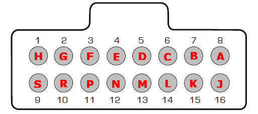
Note: Pinout is from the wiring side of the extra connector, not the terminated harness.
Pin |
REV 1 |
REV 1 usage |
REV 2 Note |
REV 2 |
REV 2 usage |
REV 2 Note |
1 (H) |
+5V power supply |
|
|
+5V power supply |
|
|
2 (G) |
INJ 8 |
Not available on STREET |
Sensor GND |
|
|
|
3 (F) |
INJ 7 |
Not available on STREET |
INJ 7 |
Not available on STREET |
||
4 (E) |
GPO 8/TACHO |
|
GPO 8/TACHO |
|
||
5 (D) |
GPO 7/DIN3 |
Not available on STREET |
GPO 7/DIN3 |
Not available on STREET |
||
6 (C) |
GPO 6 |
Not available on STREET |
GPO 6 |
Not available on STREET |
||
7 (B) |
GPO 3 |
Parallel wired with VANOS connector |
GPO 3 |
Parallel connected with VANOS connector |
||
8 (A) |
GPO 2 |
GPO 2 |
||||
9 (S) |
CAN L |
|
CAN L |
|
||
10 (R) |
CAN H |
|
CAN H |
|
||
11 (P) |
AIN 4 |
AIN 4 |
||||
12 (N) |
AIN 3 |
AIN 3 |
||||
13 (M) |
AIN 2 |
AIN 2 |
||||
14 (L) |
AIN 1 |
AIN 1 |
||||
15 (K) |
DIN 2 |
DIN 2 |
||||
16 (J) |
DIN 1 |
DIN 1 |
Note: if your cable harness is unmarked, consider it REV 1.
Pin |
REV1 function (unmarked harness) |
REV2 function |
1 (A) |
+12V ignition coils power supply |
|
2 (B) |
Alternator pin 3 (battery +), cable marked 12/5 |
Engine ground |
3 (C) |
Alternator pin 1 (light), cable marked 12/4 |
GPO 2 |
4 (D) |
Alternator pin 2 (ignition +), cable marked 12/3 |
GPO 1 |
5 (E) |
||
6 (F) |
Engine starter (+12V) - Connect to ignition key or switch |
|
7 (G) |
+12V ECU power supply |
|
8 (H) |
Engine starter (+12V) - Connect to ignition key or switch, cable marked 12/11 |
Alternator pin 2 (ignition +) |
9 (J) |
+12V ignition coils power supply, cable marked 12/10 |
Alternator pin 1 (light) |
10 (K) |
+12V ECU power supply, cable marked 12/9 |
Alternator pin 3 (battery +) |
11 (L) |
Engine ground, cable marked 12/8 |
|
12 (M) |
Extra information
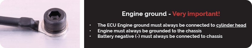
Note: Ground is important...