Extends any MaxxECU with PWM (high current) output (s)
Note: Up to 4 PWM modules can be installed and controlled on a single MaxxECU.
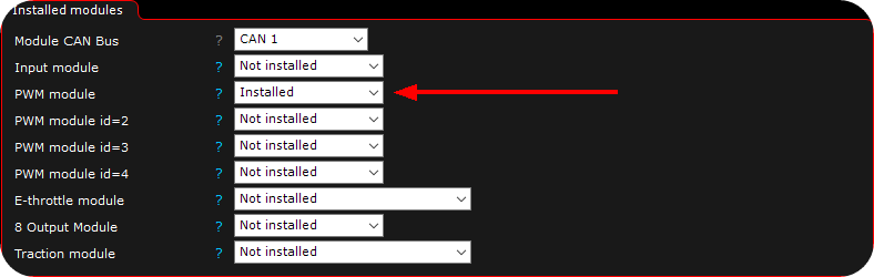
1. Activate the PWM module. (different module ID exist to be able to have more than one PWM module in a vehicle, see below).
Hardware module ID changing (only on REV3+ units)
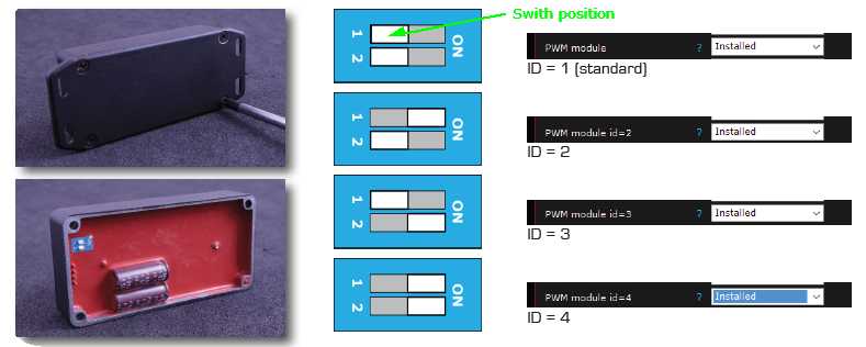
Examples of CAN hardware ID changing.
Water pump control example.

Output --> Output config, output configuration for the PWM module, set to suit your need.

Outputs --> Waterpump PWM Ctrl, set to target temperature and MaxxECU will regulate waterflow to achieve the target temperature (80deg C).
Note: This will also run the pump with intervals during the first 5minutes even if not started.
Fuel pump control example.

Output --> Output config, output configuration for the PWM module, set to suit your need.
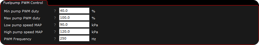
On Output --> Fuelpump PWM Ctrl. Set options to suit your need.
FAN control example.

Output --> Output config, output configuration for the PWM module, set to suit your need.
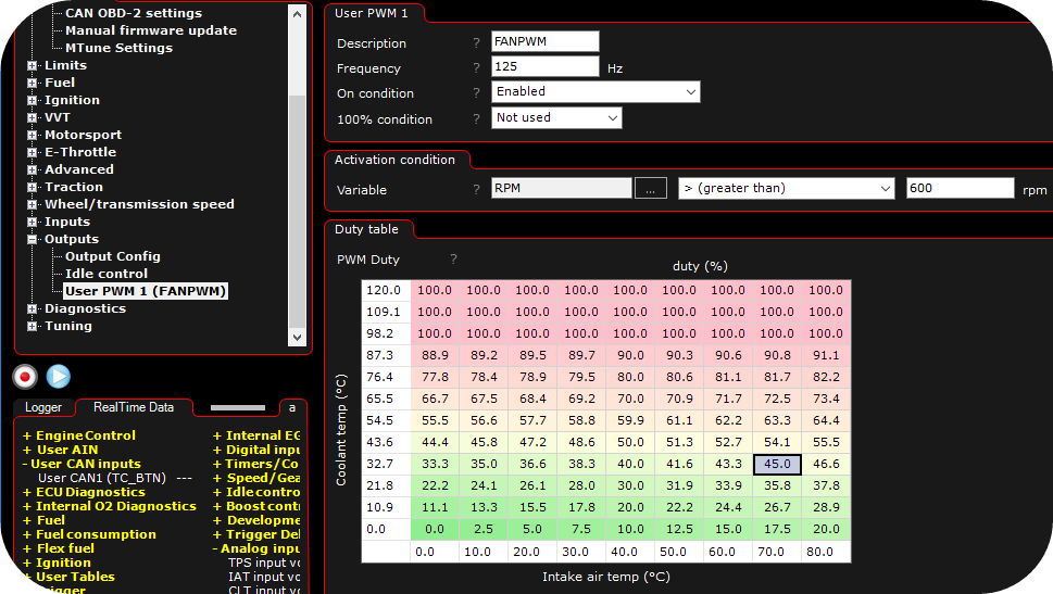
Outputs --> User PWM 1. In the above example we have a engine fan wired to the PWM module. The speed of the fan is controlled by, in this case Coolant temp (CLT), Intake air temp (IAT) and also engine speed.
CAN communication
Note: For any other CAN module manufacturer who wants to implement our protocol.
PWM Module output message
Module 1: CAN STD ID 0x111
Module 2: CAN STD ID 0x112
Module 3: CAN STD ID 0x113
Module 4: CAN STD ID 0x114
DLC = 5 bytes
Byte |
Content |
Scaling |
0 |
Temperature, low byte |
40 = -40C, 380 = 130C |
1 |
Temperature, high byte |
|
2 |
Current, low byte |
2048 = 0A, 4095 = 50.00A |
3 |
Current, high byte |
|
4 |
Error status |
0 = OK, 1 = overload |
PWM Module input message
Module 1: CAN STD ID 0x301
Module 2: CAN STD ID 0x302
Module 3: CAN STD ID 0x303
Module 4: CAN STD ID 0x304
DLC = 4 bytes
Byte |
Content |
Scaling |
0 |
Frequency, low byte |
20 – 1000 = frequency in Hz |
1 |
Frequency, high byte |
|
2 |
Duty, low byte |
0 = 0%, 1000 = 100.0% |
3 |
Duty, high byte |
Note: Needs to be sent at least at 10 times per second, if not the output will turn off.