Function to send CAN data from MaxxECU to connected peripherals, like CAN VNT turbos or a dash from another vehicle (engine swap applications) where CAN data is known.
A CAN analyzer must be used to "sniff" vehicle CAN, if the CAN ID/data are not known, example of a good and simple CAN analyzer: www.cananalyser.co.uk/
For more information regarding CAN bus: wikipedia.org/wiki/CAN_bus
CAn output value
Enable
Enable or disable the function.
CAN BUS
Specifies which CAN bus to use (more than one CAN bus is only available in MaxxECU PRO).
CAN message id type
•11bit (normal) frame identifier.
•29bit (extended) frame identifier.
can message id
Message ID (decimal value) to send.
Message rate
Specifies message rate of the message ID on the the selected CAN bus.
•1/5/10/20/50/100/200hz - Uses a fixed message rate.
•1/5/10/20/50/100/200hz when trigger value > 0 - Uses a selected RealTime Data value to start transmit at a certain rate when above the value 0.
•When trigger value changes - Uses a selected RealTime Data value to transmit at the needed rate when the value changes.
Trigger RT-Value
Specifies which RealTime Data value to use a trigger for the message rate option.
Endian
Big-endian and little-endian are terms that describe the order in which a sequence of bytes are stored in computer memory.
•Big-endian is an order in which the "big end" (most significant value in the sequence) is stored first (at the lowest storage address).
•Little-endian is an order in which the "little end" (least significant value in the sequence) is stored first.
Values in this package
Specifies number of data values to be sent in this message ID. 1-8
Data value
Value conversion mathematical formula
output Value = (Indata*Multiplier/Divider) + OFFSET
Type
•Signed variables, such as signed integers will allow you to represent numbers both in the positive and negative ranges.
•Unsigned variables, such as unsigned integers, will only allow you to represent positive numbers.
Note: Be sure to use correct 8 (1 byte) or 16 bit (2 byte) and be sure not to overlap output...
Variable
The values are sent with the internal MaxxECU resolution.
Warning/Note: When using a MaxxECU RealTime Data value in any in or output function, including comparing, the resolution (scaling) on all the values involved needs to use the same resolution values.
In short, always try to use the same resolution all over the sensors and tables. 0.1 is the most used resolution used across whole MaxxECU.
Offset
Offset to be used on the value after all conversion has been made.
Multiplier
Multiplier value.
Divider
Divider value.
Example
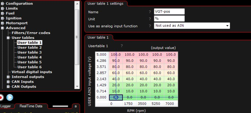
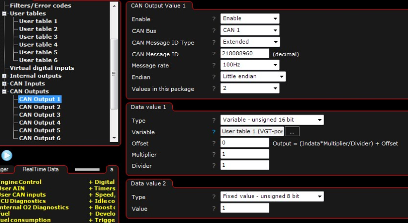
In the below example we will control a Holset HE351VE (CAN controlled VNT turbo) with MaxxECU.

In this example we are using an potentiometer wired to AIN 3 analog input and we use that value as a source axis in a user table to actually move try to move the VNT turbo.

In the above example we use the user table 1 (above) as a Variable.
Note: To control external peripherals you need to know what to send, how to send it and how fast, and also fully understand how the CAN protocol works.


