Note: When E-Throttle is activated in MaxxECU, the TPS value is now the actual pedal position, see main throttle position values in RealTime Data for actual throttle positions.
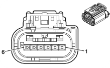
Bosch 0 280 750 474
Pin |
MaxxECU |
1 |
Motor - |
2 |
Sensor GND |
3 |
+5V power supply |
4 |
Motor + |
5 |
TPS 2 (Analog input x) |
6 |
TPS 1 (Analog input x) |
Audi S3/A4 throttle body (Bosch 0280 750 009)
Pin |
MaxxECU |
1 |
TPS 1 (Analog input x) |
2 |
Sensor GND |
3 |
Motor - |
4 |
TPS 2 (Analog input x) |
5 |
Motor + |
6 |
+5V power supply |
Audi RS6 (077133062)
Pin |
MaxxECU |
1 |
TPS 1 (Analog input x) |
2 |
Sensor GND |
3 |
Motor - |
4 |
TPS 2 (Analog input x) |
5 |
Motor + |
6 |
+5V power supply |
Corvette LS2 throttle body 90mm (12570790)
Pin |
MaxxECU |
A |
Motor - |
B |
Motor + |
C |
Sensor GND |
D |
TPS 1 (Analog input x) |
E |
+5V power supply |
F |
TPS 2 (Analog input x) |
Chrystler throttle body 80mm (53032801AC / A2C53255142)
Pin |
MaxxECU |
1 |
TPS 1 (Analog input x) |
2 |
Sensor GND |
3 |
Motor + |
4 |
TPS 2 (Analog input x) |
5 |
Motor - |
6 |
+5V power supply |
Ford Barra FG/FGX 2008 - 2016 (8R29-9F991-AA)
Pin |
MaxxECU |
1 |
Motor - |
2 |
Motor + |
3 |
TPS 2 (Analog input x) |
4 |
Sensor GND |
5 |
+5V power supply |
6 |
TPS 1 (Analog input x) |
Note: The backup signal is maxed out (100%) at 50% MAIN signal, so backup sensor output type must be backup vs. main table in E-Throttle --> Throttle position, backup/error checking.
Ford Mustang Coyote 5.0 E-throttle body (2011-2014).
Pin |
MaxxECU |
1 |
Motor + |
2 |
Motor - |
3 |
TPS 1 (Analog input x) |
4 |
Sensor GND |
5 |
+5V power supply |
6 |
TPS 2 (Analog input x) |
Note: The backup signal is maxed out (100%) at 50% MAIN signal, so backup sensor output type must be backup vs. main table in E-Throttle --> Throttle position, backup/error checking.
GM 12678223 (SENT protocol)
Pin |
MaxxECU |
1 |
Motor + |
2 |
Motor - |
3 |
DIN 1 (SENTS signal) |
4 |
Sensor GND |
5 |
+5V power supply |
6 |

The GM 12678223 E-Throttle body connector pin assigment.
SENT protocol input MTune settings.
Mitsubishi EVO X

Pin |
MaxxECU |
1 |
Motor + |
2 |
Motor - |
3 |
Sensor GND |
4 |
TPS 1 (MAIN) (Analog input x) |
5 |
+5V power supply |
6 |
TPS 2 (BACKUP) (Analog input x) |
Nissan Patrol TB48 Y61

Subaru Impreza V1 08-14
Pin |
MaxxECU |
1 |
Motor + |
2 |
Motor - |
3 |
TPS 2 (Analog input x) |
4 |
+5V power supply |
5 |
Sensor GND |
6 |
TPS 1 (Analog input x) |
VDO 408-242-002-008Z (BMW)
Pin |
MaxxECU |
1 |
TPS 1 (Analog input x) |
2 |
+5V power supply |
3 |
Motor + |
4 |
TPS 2 (Analog input x) |
5 |
Motor - |
6 |
Sensor GND |
Volvo E-throttle body (Volvo V70 08/09 (Bosch 0280 750 156)) / Bosch 0280 750 473.
Pin |
MaxxECU |
1 |
Motor - |
2 |
Sensor GND |
3 |
+5V power supply |
4 |
Motor + |
5 |
TPS 2 (Analog input x) |
6 |
TPS 1 (Analog input x) |
Software configuration (RACE/PRO example)

Inputs --> AIN x-x (0-5V)
See also, Throttle position.
How to identify the pinout of an E-throttle body if now known
1.Measure the resistance between all pins and find the two with 0.1 to 10 ohms resistance. These are the motor.
2.Test the other four pins in the same way. Find the two pins where the resistance is almost constant when opening and closing the throttle. Usually in the 1-10k ohm range. These are "Sensor GND" and "5V". (It doesn't matter which is which). If more than two pairs have constant resistance, choose the pair with the lower resistance.
3.The two pins that are left are output 1 (MAIN) and 2 (BACKUP).
Note: If there isn't continuity between the four pins that isn't the motor, or if the resistance is above 10k it's likely an active circuit that can't be identified with this method.