This is the most common question we get is about triggers and how to set them up.
MaxxECU needs a crankshaft trigger sensor to control fuel and ignition properly and the system needs to be aware of the type of trigger system being used.
Some trigger system also requires a HOME/CAM input to work, and in addition to for ex. a Missing tooth system, fuel and ignition can be sequential.
Wheels and triggers:
•Concentric (within 0.1mm(0.004").
•Robust trigger bracket.
•Trigger wheel not mounted on damper or other flexible material on crank.
•Made of magnetic material (steel, not stainless or aluminum), in order for the sensor to read it's tooth's.
•Use factory trigger setup if possible, except Nissan CAS or Mitsubishi EVO 4/2 which is not recommended for high horse applications.
MaxxECU has a built-in tools for trigger diagnostics:
• Trigger Oscilloscope <-- Please read and understand this tool before continuing.
The scope is used to:
•Check the input voltages of both digital and VR-sensors.
•Set the arming voltages for VR-sensors.
•Check the polarity of VR-sensors.
•Check for zero-crossing problems on VR-sensor.
•Check the relationship between the Crank and Cam sensors in some special cases (multitooth+home like the 2JZ and similar triggers).
The scope is NOT the tool to tell anything about the actual pattern on the trigger wheels. It can be used to tell basic stuff like if the inputs are swapped, but to analyze the patterns we use the Trigger Logger.
The trigger logger can be used to:
•Tell what pattern the trigger wheel on the crank and cam has
•See trigger problems caused by compression, bad trigger wheels, interference etc.
See, Trigger Logger for more information about the important trigger logger.
How to use the trigger oscilloscope
Examples of what settings might be used to set by using the built-in trigger oscilloscope.
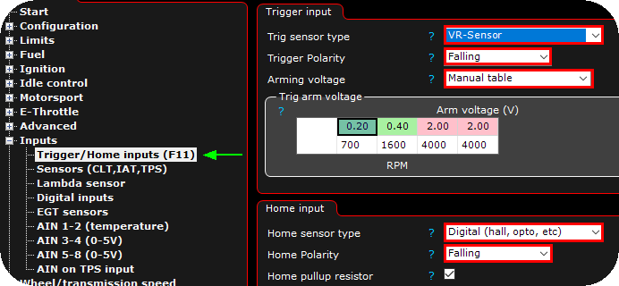
1. Use the Trigger Oscilloscope to set the Trigger Input and Home Input sections. (Digital/VR, polarity and arming voltages).
Note: When cranking, start at 200ms, that's about 1 revolution at normal cranking speed (if the data is to compressed try lowering the time (necessary for wheels with lots of teeth)).
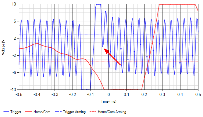
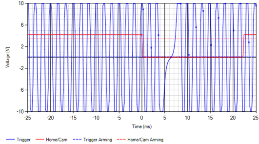
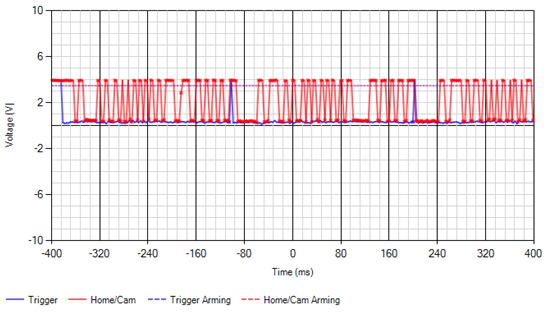
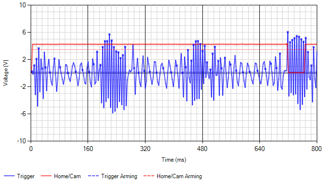
In the above we can see that the Trigger (crank) is a VR-signal and the HOME/CAM is a digital signal.
From the VR-signal we can tell:
•It has lots of voltage, we can set the ARM voltage high to make it less sensitive to interference.
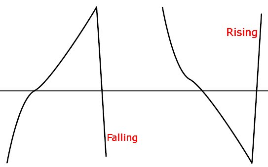
•The polarity is FALLING, because that's it that's the fastest "edge" during the missing gap (rises slowly, falls fast)
From the digital signal we can tell:
•The voltage from the sensor is OK (it needs to be above the dotted red line, and then fall to about 0V).
•The polarity if digital signals can't often be determined from the scope.
Digital signal polarity:
• There are cases where it should be the edge farthest away from a crank wheel edge.
• In some cases, it's dependent on the selected Trigger system.
• In most cases, it doesn't matter for digital signals.
Common problems that can be seen in the scope:
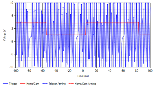
Sampling time to long for the signal, looks compressed and uneven.
Sampling time to long, trigger-dots but no matching waveforms.
Incorrect polarity, it triggers on the falling edge, but it should be on the rising edge.
To long sampling time, many trigger dots that doesn't match the waveform. There's also more signals on the CAM input than on the CRANK, indicating that the CAM and CRANK inputs most likley are swaped.
|
• Trigger Logger <-- Please read and understand this tool before continuing.
The trigger logger can be used to:
•Tell what pattern the trigger wheel on the crank and cam has.
•See trigger problems caused by compression, bad trigger wheels, interference etc.
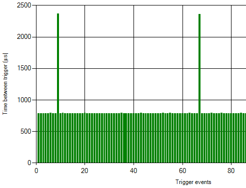
The trigger logger graphs the times (in microseconds) between each trigger signal received by the ECU. For this to show reliable results the trigger inputs need to be set up properly for the ECU to correctly trigger on the inputs.
The Trigger Logger doesn't care at all about the trigger system or its settings, just the trigger inputs (the Trigger input and Home input sections).
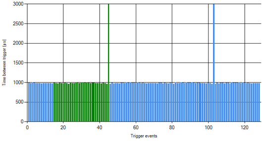
Note: Green and Blue mean the ECU doesn't have any trigger problems (but there could still be problems it's not seeing). Orange indicates some problem.
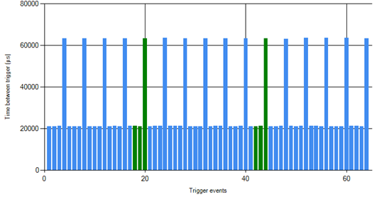
Example of a good trigger pattern.
In the above image we can see that it has a pattern of 3 short and 1 long pulse. Remember that these are the times between the trigger signals. What would this wheel actually look like? From the "lots of short and one long", we can conclude that it's a missing tooth wheel.
The missing gap is about 3 times as long as the regular teeth. That means that there are TWO missing teeth (if were ONE missing tooth the time would be about 40000µs).
The total number of teeth including the missing would be 3(the short ones)+1(the long one)+2(the missing ones), so 6 teeth.
This pattern is 6-2.
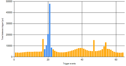
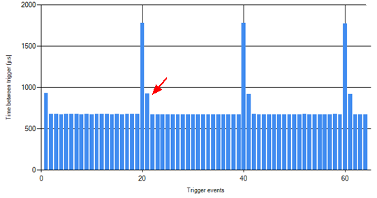
Example of a trigger loggers with problems
The small wave in the signal is the engine compression, the engine slows down a little during compression (which is totally fine for the ECU). BUT, there's a lot of triggers that are too long and it doesn't look like a pattern.
What's happening here is that the arming voltage is set to high and the ECU "misses" some of the triggers, so it registers several short signals as one long. This is not going to work.
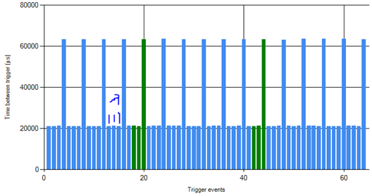
The tooth after the missing is a little longer than expected. This is probably caused by incorrect polarity.
A good looking 60-2 trigger logger (57 short, 1 long, about three times longer than the other teeth)
This is when running, when cranking there's usually more variation in the pattern.
If the trigger pattern here looks irregular or has spikes and gaps in it, there's no way for the ECU to "sync" to the pattern and register RPM. Before continuing and trying to set up the trigger system (60-2 etc), we would need to figure out what the problem with the input signal is.
|
Trigger oscilloscope (Diagnostics --> Trigger oscilloscope)
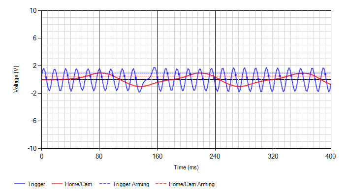
This built-in feature indicates what MaxxECU "sees" in the trigger inputs.
MTune built-in tool for trigger diagnostics.
In the above image we can clearly see a missing tooth trigger wheel pattern (blue line), and a HOME/CAM sensor signal (red line).
The "dots" in the image is the approx position where MaxxECU triggers (the actual trigger point is the zero crossing, or ~1.1V for digital triggers).
Trigger polarity explained
MaxxECU must know if you want to trigger on the "signal way up" or the "signal way down", this is also called rising and falling trigger.
A general rule is that we want to trigger on the "shortest and most distinct signal direction".
Note: Sometimes (especially on digital signals) the position of the HOME/CAM can be "adjusted" by changing the trigger polarity, if for some reason the HOME/CAM signal is to close for ex the "missing tooths". <-- Ensure that HOME/CAM position is distinc far from any missing teeths.
An illustration of the difference between rising and falling curves.
Trigger arm voltages and how to determine
Since MTune 1.99, the trigger oscilloscope have additional information because of the new automatic tracking arming voltage feature.
Note:Trigger arm settings is only available when using a VR-sensor, and the recommended way is to set up the arming voltage in a manual way.
A good recommendation is to use 50% of the highest voltage as the trigger arm at current engine RPM.
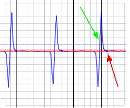
The automatic trigger arm tracking feature. The blue and red "dotted" lines represents the actual voltages where MaxxECU triggers.
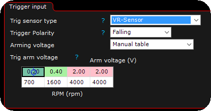
When using manual table, you tell MaxxECU on which trigger voltage to actually arm it as a signal from the sensor.
Advanced trigger options (only for Missing tooth trigger system)
Since MTune 1.100 we added an extra tolerance at low RPM trigger options, especially for high compression and small engines such as 3-cylinder motorcycle engines.
A common signal from high compression small engines during crank.
Inputs --> Trigger/Home inputs, Advanced trigger options.
Adaptive cranking tolerances (for small high compression engines)
Note: DO NOT ENABLE THIS UNLESS YOU HAVE A PROBLEM, ENABLING IT "JUST IN CASE" IS NOT AN OPTION.
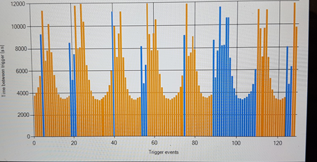
If you trigger logger looks like this during cranking, the new adaptive cranking tolerances can be enabled, otherwise DO NOT USE IT.
|
Trigger logger (Diagnostics --> Trigger logger)
This built-in feature is using the trigger settings to reflect the trigger pattern which is used by MaxxECU.
Each bin represent the time between each trigger input to the system, in the above example, a 60-2 trigger wheel is used, therefore there should be 58 "equal" height of bins before there is a three times higher bin, which represents the "missing tooth" space.
Note: Green and Blue mean the ECU doesn't have any trigger problems (but there could still be problems it's not seeing). Orange indicates some problem.
Using the Live-logger when dealing with trigger issues or trying to get engine RPM
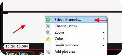
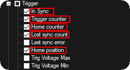
1. Right click on the live-logger area, click on Select channels.
2. Check the above values, and confirm by pressing the OK button.
Note: RPM is also a good value to see...
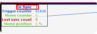
3. During cranking or an running engine, the In Sync value should always be "1".
Note: In sync = "0" means the trigger system is not synced, and will never fire either ignition or injectors.
Depending on which trigger system you are using, also check that Trigger counter increase during cranking, if you have a home/cam sensor, make sure the Home counter increasing during cranking.
Typical problems and solutions
No zero voltage crossings
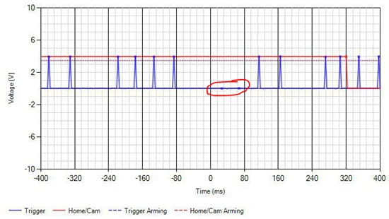
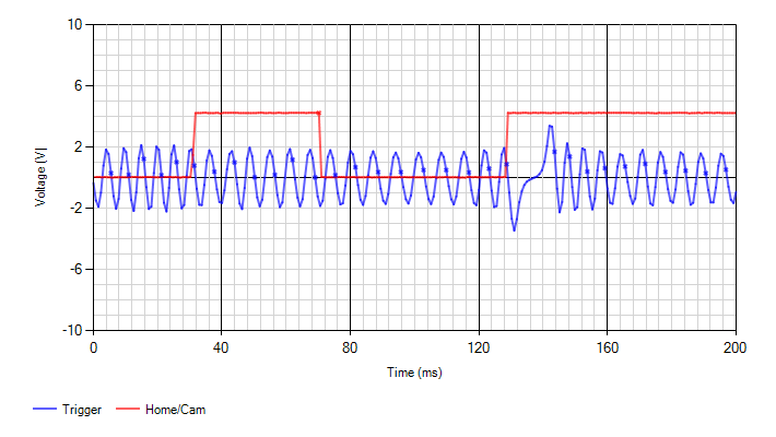
When a trigger signal (blue line) looks like the above, it will most likely generate a trigger error because the signal does not have a zero voltage crossings, it is most likely because the voltage from the sensors suddenly gets a spike, and MaxxECU protects itself and the result can be a "magnetized" sensor.
A solution (in most cases) to fix the above is to mount an external ~3K ohm resistor in series with the trigger output signal and the MaxxECU trigger input.
Built-in tools
•Trigger Oscilloscope. <-- Please read and understand this tool before continuing.
•Trigger logger. <-- Please read and understand this tool before continuing.
 Trigger Oscilloscope <-- Please read and understand this tool before continuing.
 Trigger Logger <-- Please read and understand this tool before continuing.
