Compatible with MaxxECU STREET/V1/RACE/PRO
Harness support
Terminated engine harness |
MaxxECU I/O |
Note |
+12V to injectors, ignition and valves |
Yes |
|
Cylinder head GND |
Yes |
|
OEM generator |
Yes |
|
OEM engine starter |
Yes |
|
Injectors (Bosch JPT connectors) |
INJ |
|
Ignition (VAG 1.8T coil-on-plug) |
IGN |
|
OEM intake temperature sensor |
IAT |
|
OEM coolant temperature sensor |
CLT |
|
OEM throttle position sensor |
TPS |
|
OEM idle stepper motor |
GPO: 4,5,6,7 |
Not available on MaxxECU STREET |
OEM crank trigger |
TRIGGER |
|
OEM CAM trigger |
HOME |
|
Variable valve solenoid (VVTi) |
INJ 8 |
Not available on MaxxECU STREET |
Boost solenoid |
GPO 3 |
|
Fuel pump control |
Use available GPO in extra connector |
|
Engine FAN control |
Use available GPO in extra connector |
|
MAP sensor hose in harness |
Yes |
|
Wideband LSU connector |
Yes |
LSU 4.2 |
Installation
The installation of the terminated engine harness is pretty straight-forward.
1.Mount all engine connectors.
2.Place VAG coils (not included) and connect to harness. wired for SHORT VAG coils!!!!
3.Connect all injector connections (JPT connectors).
4.Route harness thru firewall and mount MaxxECU.
5.Wire battery, power, ground, alternator and engine starter to 12-pin connector.
6.Wire extra connections like fuel pump, fan, wheel speeds, ethanol sensor etc to 16-pin connector.
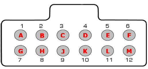
12-pin connector (seen from the wire side)
Please note that REV1 (unmarked harness) pinout is mirrored, please check the printed labels on the cables which is correct!!

Note: Pinout is from the wiring side of the connector, not the factory pre-wired side.
Pin |
REV1 function (unmarked harness) |
REV2 function |
REV3 function |
1 (A) |
+12V ignition coils power supply |
+12V ignition coils power supply |
|
2 (B) |
Alternator pin 3 (battery +), cable marked 12/5 |
Engine ground |
GND |
3 (C) |
Alternator pin 1 (light), cable marked 12/4 |
GPO 2 |
GPO 2 |
4 (D) |
Alternator pin 2 (ignition +), cable marked 12/3 |
GPO 1 |
GPO 1 |
5 (E) |
- |
||
6 (F) |
Engine starter (+12V) - Connect to ignition key or switch |
Engine starter (+12V) - Connect to ignition key or switch |
|
7 (G) |
+12V ECU power supply |
+12V ECU power supply |
|
8 (H) |
Engine starter (+12V) - Connect to ignition key or switch, cable marked 12/11 |
Alternator pin 2 (ignition +) |
Alternator pin 2 (ignition +) |
9 (J) |
+12V ignition coils power supply, cable marked 12/10 |
Alternator pin 1 (light) |
Alternator pin 1 (light) |
10 (K) |
+12V ECU power supply, cable marked 12/9 |
Alternator pin 3 (battery +) |
Alternator pin 3 (battery +) |
11 (L) |
Engine ground, cable marked 12/8 |
- |
|
12 (M) |
- |
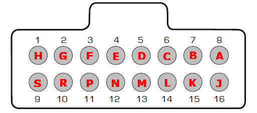
16-pin connector (seen from the wire side)
Please note that REV1 (unmarked harness) pinout is mirrored, please check the printed labels on the cables which is correct!!

Note: Pinout is from the wiring side of the connector, not the factory pre-wired side.
Pin |
REV1 function (unmarked harness) |
REV2 function |
REV3 function |
1 (H) |
CAN H, grey cable |
DIN 2 |
CAN H, grey cable |
2 (G) |
CAN L, pink cable |
DIN 1 |
CAN L, pink cable |
3 (F) |
GPO 1, cable marked 16/6 |
GPO 8/TACHO |
- |
4 (E) |
GPO 2, cable marked 16/5 |
INJ 7 - Not available on STREET |
INJ 7 - Not available on STREET |
5 (D) |
INJ 7, cable marked 16/4 - Not available on STREET |
- |
|
6 (C) |
GPO 8/Tacho, cable marked 16/3 |
- |
GPO 8/Tacho |
7 (B) |
Digital input 1, cable marked 16/2 |
CAN L |
DIN 1 |
8 (A) |
Digital input 2, cable marked 16/1 |
CAN H |
DIN 2 |
9 (S) |
AIN 1, cable marked 16/16 |
GND |
AIN 1 |
10 (R) |
AIN 2, cable marked 16/15 |
+12V extra power |
AIN 2 |
11 (P) |
AIN 3, cable marked 16/14 |
SENSOR GND |
AIN 3 |
12 (N) |
AIN 4, cable marked 16/13 |
+5V sensor supply |
AIN 4 |
13 (M) |
+5V power supply, cable marked 16/12 |
AIN 4 |
+5V power supply |
14 (L) |
Sensor GND, cable marked 16/11 |
AIN 3 |
Sensor GND |
15 (K) |
+12V power supply, cable marked 16/10 |
AIN 2 |
+12V power supply (connected to 12-pin, 7) |
16 (J) |
Engine ground, cable marked 16/9 |
AIN 1 |
GND |
Extra information

Note: Ground is important...