Terminated engine harness for Volvo V70N (2000 - 2008) engine with reservations for change of sensors during the years.
Compatible with MaxxECU STREET/V1/RACE/PRO
Harness support
Terminated engine harness |
MaxxECU I/O |
Note |
+12V to injectors, ignition and valves |
Yes |
|
Cylinder head GND |
Engine GND |
|
OEM generator |
Yes |
Extra connector |
OEM engine starter |
Yes |
Extra connector |
Injectors (Bosch JPT connectors) |
INJ 1-5 |
|
Ignition (VAG 1.8T coil-on-plug) |
IGN 1-5 |
|
OEM intake temperature sensor |
IAT |
Requires external sensor |
OEM coolant temperature sensor |
CLT |
|
OEM throttle position sensor |
TPS |
|
OEM idle stepper motor |
GPO 5, GPO 4 |
Not available on MaxxECU STREET |
OEM crank trigger |
TRIGGER |
|
OEM Exhaust CAM trigger |
HOME |
|
OEM Intake CAM trigger |
DIN 1 |
|
Boost solenoid |
GPO 3 |
|
Fuel pump control |
Use available GPO in extra connector |
|
Engine FAN control |
Use available GPO in extra connector |
|
OEM VVT solenoid (intake) |
INJ 7 |
Not available on MaxxECU STREET |
OEM VVT solenoid (exhaust) |
INJ 8 |
Not available on MaxxECU STREET |
Extension for Volvo T6 engine |
INJ 6, IGN 6 |
Extra connector |
MAP sensor hose in harness |
Yes |
Length
Start |
End |
Total length |
MaxxECU CMC connector |
Firewall entry/bushing |
900mm |
MaxxECU CMC connector |
LSU connector |
1700mm |
MaxxECU CMC connector |
IGN 1 coil connector |
2100mm |
Harness connectors
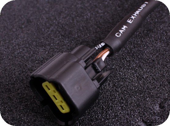
CAM sensor intake and exhaust connectors. (OEM sensor: VOLVO-30713370).
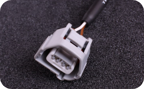
Crank trigger connector. (OEM-sensor: VOLVO-31331765).
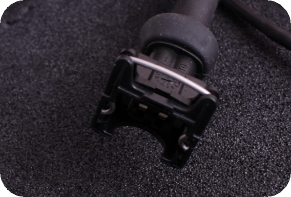
Injector (Bosch JPT 2-way) connectors.
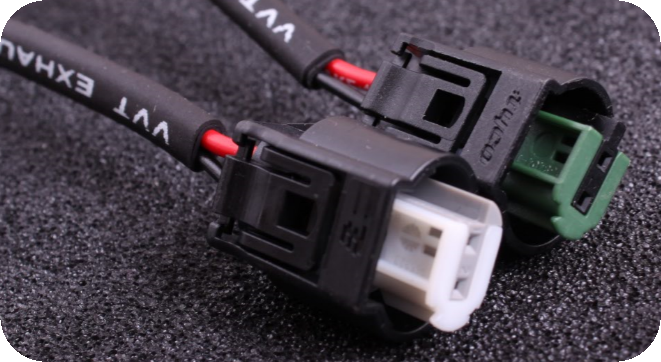
VVTi solenoid connectors. (OEM-sensors: VOLVO-36002146(exhaust), VOLVO-36002145(intake)).
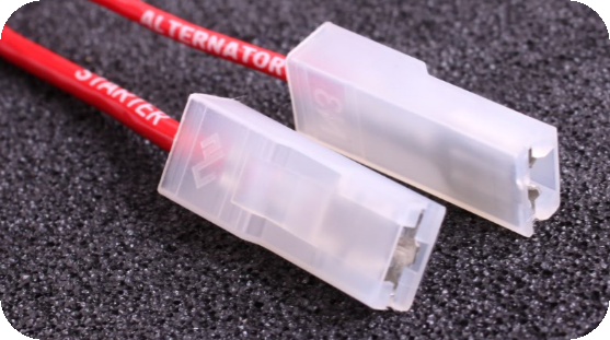
Alternator and starter connectors.
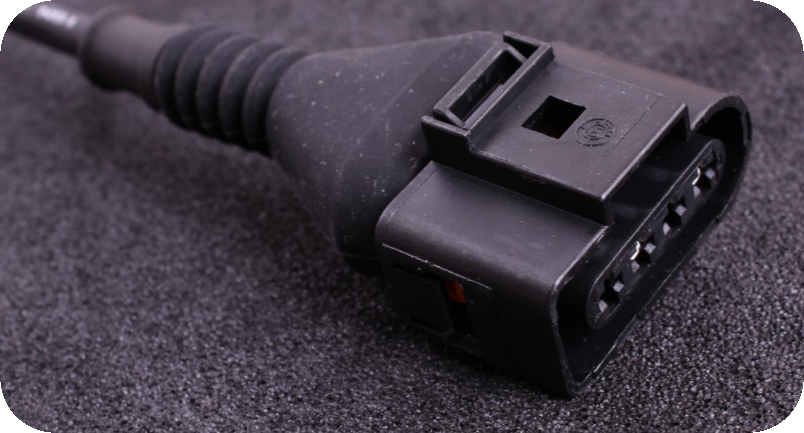
Ignition coil (VAG 1.8T) connectors.
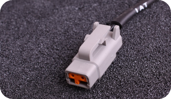
IAT connector (DTM), Volvo does not have any IAT sensor, but external sensor can be mounted in the intake manifold.
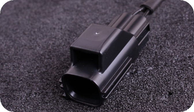
Coolant temp sensor (CLT) connector. (OEM-sensor: VOLVO-9125463).
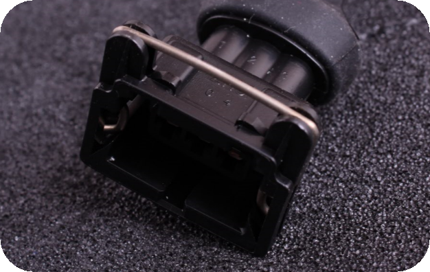
Idle valve connector (Bosch JPT 3-way)
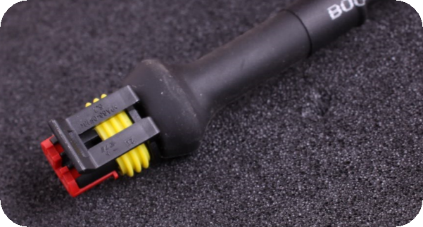
Boost solenoid connector, superseal 2-way.
Installation
The installation of the terminated engine harness is pretty straight-forward.
1.Mount all engine connectors, alternator and engine starter.
2.Place VAG coils (not included) and connect to harness. NOTE: wired for SHORT VAG coils!!!!
3.Drill a 54mm hole in the firewall for harness bushing.
4.Route harness thru firewall and mount MaxxECU. Mount position is very dependent on engine placement and vehicle model.
5.Connect +12V with external relay and fused (15A) to the extra 12-pin connector, pin 9.
6.Connect +12V with external relay and fused (15A or more depending on coils) to the extra 12-pin connector, pin 10.
7.Connect engine ground (brown wire) on cylinder head.
8.Connect alternator (pin 11 on 12-pin connector) to +12V ignition (in serial with a charge bulb).
9.Connect starter trigger (pin 5 on 12-pin connector) to start button (+12V).
10.Connect fuel pump, fan and other outputs to available GP Ouput (GPO).
11.Install optional external IAT (highly recommended).
12-pin connector (seen from the wire side)
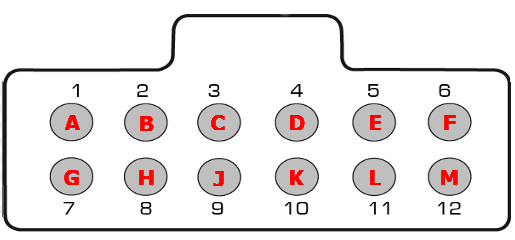
Note: Pinout is from the wiring side of the connector, not the factory pre-wired side.
Pin |
REV1 function (unmarked harness) |
REV2 function |
1 (A) |
- |
+12V ignition coils power supply |
2 (B) |
Engine GND |
|
3 (C) |
- |
|
4 (D) |
- |
|
5 (E) |
Engine starter trigger (+12V will crank the engine) |
- |
6 (F) |
- |
Engine starter trigger (+12V will crank the engine) |
7 (G) |
- |
+12V ECU power supply |
8 (H) |
Engine GND |
- |
9 (J) |
+12V ECU power supply |
- |
10 (K) |
+12V IGN coils power supply |
- |
11 (L) |
Alternator + (connects to +12V ignition via a charge light) |
Alternator + (connects to +12V ignition via a charge light) |
12 (M) |
REV 2 changed to be compatible with the MaxxECU relay and fuse box (ID 1945).
16-pin connector (seen from the wire side)
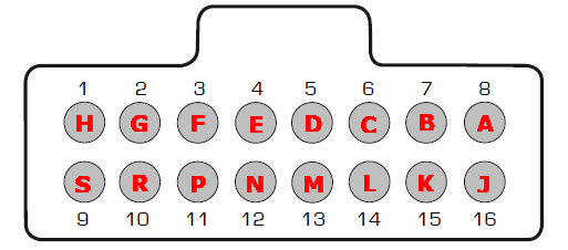
Note: Pinout is from the wiring side of the connector, not the factory pre-wired side.
Pin |
REV1 function |
REV2 function |
Note |
1 (H) |
CAN H |
CAN H |
|
2 (G) |
CAN L |
CAN L |
|
3 (F) |
Not available on STREET |
||
4 (E) |
Not available on STREET |
||
5 (D) |
- |
||
6 (C) |
|||
7 (B) |
|||
8 (A) |
Parallel connected with Intake CAM (can only be used if no CAM sensor is connected) |
||
9 (S) |
|
||
10 (R) |
|
||
11 (P) |
|
||
12 (N) |
|
||
13 (M) |
+5V sensor supply |
+5V sensor supply |
|
14 (L) |
Sensor GND |
Sensor GND |
|
15 (K) |
+12V |
+12V |
Extra +12V out (from ECU power supply) |
16 (J) |
Engine GND |
Engine GND |
Extra Engine GND (from engine head) |
6-pin connector (seen from the wire side), to easy up the Volvo T6 support...
Pin |
Description |
Note |
A |
INJ 6 |
|
B |
+12V |
|
C |
IGN 6 |
|
D |
+12V |
|
E |
Engine GND |
|
F |
- |
Extra information

Note: Ground is important...