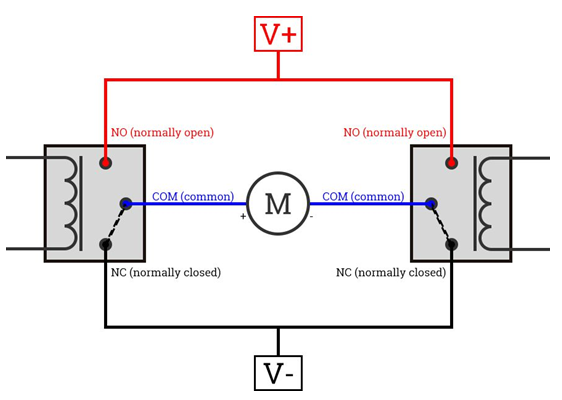
The actuator control system is used to control two direction motors actuating different accessories, for example, exhaust cutouts, variable intakes, wings etc. The actuators are intended to have two positions (this is not a variable control).
The state of the actuator is controlled by the digital input Actuator x target state. This can be a wired digital input or an internal output triggered by any user selectable conditions.
When the control input is activated, the output Actuator 1 Open/Positive/+ is active for a selectable time. When the input is deactivated again, the Actuator 1 Close/Negative/- outputs is activated for a selectable time.

Example of output configuration.
The motors can be controlled in two ways:
1. Two external relays on any GPO.
The actuators need to have built-in limit switches or current limit.
Configured like this:

2. Using a motor connected directly to the H-bridge outputs on a MaxxECU SPORT, RACE or PRO.
No relays needed, the ECU changes the motor direction, and the built-in current sensor can be used to detect and stop at the end-position (the current peaks when the actuator hits a mechanical stop).
Note: This is the preferred way to control actuators up to 5A.
Output timeout
When the control input state is changed, the corresponding output is using this amount of time (or until the current limit is reached).
Use external relays to control the actuator direction, or use two built-in H-bridge outputs (GPO11/12 or 13/14) to control the actuator direction.
Current limit/end of travel detection
Uses the current(A) to the motor to sense the end positions. When the set current is reached, the outputs are disabled until the direction is changed.
Current sensing are only available on motor/throttle outputs:
•GPO 11/12 = DBW Current 1
•GPO 13/14 = DBW Current 2
Max current
The current at which the outputs are disabled.