Knock sensors
Knock sensors
Enable or disables MaxxECU internal knock sensor functionality.
Cylinder diameter
Specifies the engine cylinder diameter.
Input sensitivity
Only available for GEN2
The GEN2 knock inputs are approximately 20 times more sensitive than the GEN1 inputs, resulting in significantly higher readings. Use this setting to reduce the displayed values and better match existing GEN1 calibrations.
•GEN1 Equivalent Readings (lower knock values - Scales down knock levels to match GEN1 calibration values.
•GEN2 Higher Sensitivity (higher knock values) - Uses full GEN2 input sensitivity, resulting in higher knock readings.
sensor assignment
Cylinder X knock sensor
Assign corresponding cylinder to correct sensor.
Examples
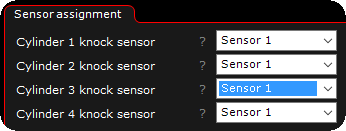
A four cylinder Volvo engine (B230 8V).
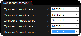
A five cylinder Volvo engine (T5).
Cylinder adjustments
Individual cylinder adjustments
Enables or disables the individual cylinder sensitivity adjustments, only used if the knock sensors values are different on different cylinders.
100% means it uses the knock sensor values on that cylinder without no correction (default value). 110% means the individual cylinder sensitivity values is raised by 10% on that particular knock sensor values seen by the ECU.
Note: Only use if 280% certain what you are doing!
MaxxECU RACE / MaxxECU PRO / MaxxECU GEN2 RACE has built-in advanced knock sensor functionality.
Note: All MaxxECUs have support for external knock functionality, more information on external knock control.
Supported sensors
•Bosch 0261 231 046 or similar 2-wire Bosch knock sensor are supported.
Note: Nissan, Toyota, GM 1-wire sensors are not supported.
How knock is detected
Knock is detected by comparing the knock sensors' gated second overtone intensity with a threshold table. A value exceeding the set threshold is considered a knock. The threshold table is manually tuned. No noise floor averaging is applied.
The knock detection window starts at the ignition event and lasts to either TDC or the next ignition event (depending on cylinder count and sensor count).
The knock intensity is the integrated sum of the second overtone of the fundamental knock frequency during the last combustion event.
Knock intensity is logged per cylinder as "Peak" and "Fast" values.
The "Fast" value is updated continuously for each cylinder.
The "Peak" value is the max value during the last 200ms. This is best used to spot peaks that may be missed in slower logs. Use these values when tuning the threshold tables. If knock is detected ignition angle is adjusted with a delay of 1-3 ignition events depending on cylinder count.
ECU logging is not synchronized to engine rotation, it's time-based with a logging rate of up to 1khz. That's enough to monitor per-cylinder fueling, knock, etc, but that's wholly unnecessary. Such fast logging is usually only used for drag racing. For knock tuning just looking at the Knock Count and Peak values with the regular live logger at 25hz is enough.
Temporary deactivation of knock features (Added in MTune 1.157)
During launch control, or if either ignition cut or fuel cut exceeds 20%, all knock-related safety functions are temporarily disabled for another 200ms.
This prevents knock control from interfering with the aggressive torque-reduction strategy used for launch or other cut events.
Detection frequency
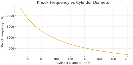
The knock frequency is inversely proportional to the cylinder bore diameter. Small engines (≈50 mm bore) typically have a knock frequency around 11–12 kHz, while large engines (≈200 mm bore) are closer to 2.8–3 kHz. This information is used to select the correct knock band-pass filter in the ECU.
WARNING: The Knock retard functionality in MaxxECU is a tool to detect engine knock, but with wrong settings it can cause engine damages. Use with caution!
Individual knock detection
A cam synced trigger system is highly recommended for a dual sensor knock sensing system.
For single sensor knock detection cam sync is optional (but the knock results might be logged on the wrong cylinder).
1. Activate and assign sensor(s)
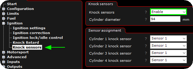
Activate knock sensor(s) in MTune, Ignition --> Knock sensors and assign sensors to the correct cylinder. In our example we are using an four cylinder Volvo B230 8V engine.
Note: The cylinder diameter is extremely important to be correct.
2. Explanation of available RealTime Data values for Knock control
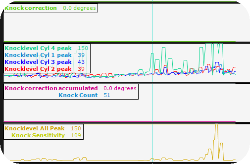
The above is a good example of handy RealTime Data values to have visible in the live-logger during Knock tuning.
Knock correction
Current (and actual) ignition retard being used right now.
Knock correction accumulated
Accumulated retard value. This is the "stored" knock retard value, it can never be bigger than Max accumulated retard value. If this value is retarded for to long period (according to you), you have to increase the advance rate table values to advance back faster.
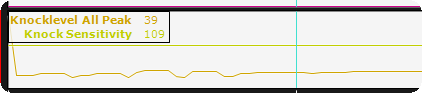
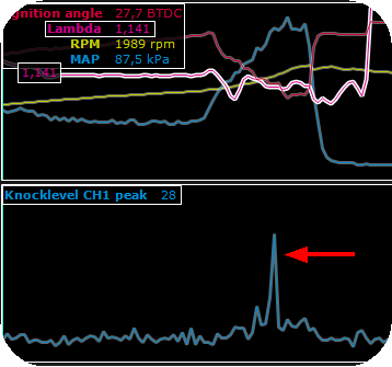
Knocklevel CYL X peak
The peak value of the individual cylinder knock(s) detected (highest value of the last 200ms of time) <-- For the tuner to easy up the task of finding knock(s) since this value will always be visible in the live-logger.
Knocklevel Cyl X FAST
Average knock level value (updates every combustion cycle) <-- Used by the MaxxECU to determine engine knock.
Note: The above FAST value is too fast to get updated in the live-logger, it must be logged using the internal logging system at 1000Hz, therefore we have the Knocklevel CYL X peak available.
3. Determine sensitivity on the knock sensors and populate the sensitivity table
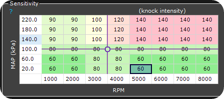
1. The above sensitivity table found in MTune, Ignition --> Knock sensing needs to be populated with YOUR engine knock signal levels.
Knocklevel cyl X peak higher than these table values --> Indication of a knock in the system, it is EXTREMELY important that this sensitivity table is populated with values from your engine when it is considering to knock. Do not copy table from a friend, NEEDS to be determined on this specific engine!
2. Do a dyno run and watch the Knocklevel Cyl X peak value when you are SURE there is no engine knock.
3. Increase ignition until you notice changes in the Knocklevel Cyl X peak (or in any of the PEAK CYL values) or hear detonation.
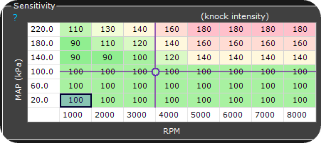
4. Populate the above sensitivity table with values you know the engine is considering knocking (preferable right before knock value) in the different load and speed axis. MaxxECU will use this threshold when detecting knock and retard timing to prevent more detonations.
Note: MaxxECU is using the Knocklevel FAST value, not the knocklevel peak.
4. Basic settings
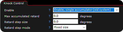
Max accumulated retard
The maximum retard the system can ever make.
Retard step size
Number of degree to retard when each knock is detected (by using the sensitivity table).
Retard step mode
Specifies whether to use a fixed retard value for each knock, or use an progressive mode.
•fixed size - Always retards the same amount for each knock event.
•progressive - Decreases the amount of retard for frequent knock events to prevent retarding too much. The minimum step size is 20% of the entered retard step size value when this setting is used.
5. Retard range table
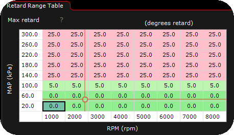
Fill the above table with maximum retard angles at different load and speed considered to be safe for your particular engine.
Note: The Max accumulated retard is always the max ignition retard that can be made, regardless of the above table. In the above example, the "25" value from the table is never used since Max accumulated retard is "10" in our example.
6. Advance rate table
The table that advances back the retarded ignition timing to the normal level at a given rate, each second, specified in degrees/second.
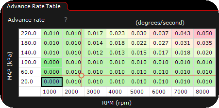
The advance rate table, specifies the rate (degrees per second) the system will advance back the already retarded ignition timing (from the knock correction accumulated value) per second, when the knock values are below the values in the sensitivity table (which means the engine is not knocking).
An example rate of 1 degree/second means if the system has detected knock and retarded 10 degrees, it takes 10 seconds for the system to get back to normal ignition curve, if no further knock is detected during this time period.
In the above example at the red cursor, an advance rate of 0.010 degrees/second is used, which means it takes 100 seconds to advance back 1 degree of timing.
Note: During testing, please use a higher value ("5" or similar) in the idle/low area to "get back to normal ignition timing" as fast as possible.