Required sensors for power management
The system is based on the "Driven wheelspeed" values. This can be from rear wheel sensors or from a driveshaft speed sensor.
The input need to be setup in update rate = High speed mode. With little to no filters active, see driveshaft speed sensor.
The sensor can have any number of teeth, but more teeth give better performance.
•For sensors mounted to the wheels: 32 or more teeth.
•For drive shaft mounted sensors: 8 or more teeth.
Note: It's important that the trigger wheels and sensor mounts are precision machined, as any deviation in the pattern or sensor vibration can cause the speed value to fluctuate.
Power management
Enable
•Disabled
•Enabled, always on
•Enabled, by digital input - Uses the Power management system enable digital input.
Time after launch Timer start mode
Selects how the "Time after launch" timer is started.
•Launch control input release - Uses the launch control switch, enable stage x digital input.
•Launch control release - Starts the timer whenever the launch control gets deactivated.
•Clutch switch input release - Uses the clutch switch digital input.
•Transbrake input release - Uses the transbrake hold digital input.
•sensed speed - Will start the timer when a vehicle speed is detected, mostly used in combination with the launch control activation mode always active (disabled by speed).
Power management settings
time after launch power limit (enable/disable)
This is a time based retard and cut system that can be used with or without speed sensors (active power management).
Uses predetermined ignition retard and engine cut values based on the time after launch. Used to optimize the traction right after the launch.
Speed based active power management (enable/disable)
Uses a target speed table to restrict the engine by ignition retard and fuel/ignition cut to reach a predetermined acceleration curve.
Cut method
Specifies power cut method
•Ignition - Drop ignition and/or retard ignition timing advance from the below tables.
•Fuel - Drop fuel to reduce engine power. <-- use with caution.
Disable above gear
Used to disable the system over a set gear. Used with manual transmission where the system can't be used above a certain gear.
Disable above speed
Used to disable the system over a set speed. Used with manual transmission where the system can't be used above a certain speed.
allow ignition advance
Specifies whether to allow the system to ignition advance to gain more power to reach speed target, or only use ignition retard.
•No (only retard the ignition angle - Only ignition retard is allowed..
•enable (the system can add more advance than in the base ignition table) - Both ignition retard and ignition advance is allowed!
Activation mode
Specifies the activation mode of the power management feature.
•Time after launch timer start - Activates when the time after launch timer starts.
•Always active - Power management is always active, regardless of the time after launch. It can be used as a traction control system.
Time after launch power limit
Merged with the older After launch power limit (ALPL) function, check your settings really carefully after update!
Functionality to reduce engine power (and optimizer starts in drag racing applications) after launch control and ramp power back during a specific time-period.
Note: This functions requires the launch control function to be used.
Cut table
Power limit with "event drop" vs time after launch. 100% = shut off.
Note: The last (most right) cell MUST be 0 degree.
retard table
Specifies ignition retard vs time after launch. Specified as positive values.
Note: The last (most right) cell MUST be 0 degree.
Speed based active power management (power cut)
Target source
Specifies how the target speed is entered in the below target speed table.
•Driven wheel speed - Can be used even if only a driveshaft sensor is used. The speed is automatically calculated from the driveshaft RPM, gear ratio and tire size. <-- recommended.
•Drive shaft RPM - .
Target speed
Uses a target speed table to restrict the engine power by the above cut method to reach a predetermined acceleration curve. Import of data from a logfile is possible as a starting point, see below examples.
Target RPM
Uses a target RPM table to restrict the engine power by the above cut method to reach a predetermined acceleration curve. Import of data from a logfile is possible as a starting point, see below examples.
target speed correction table
Used to add or subtract from the target table. For example when on gear changes.
Cut table
The engine cut and retard is determined by the deviation from the target speed.
The retard can be negative (ie. adding timing). But the timing overall timing adjustment from both the active power management and after launch limiter cannot advance the timing, only retard it.
Retard table
The engine cut and retard is determined by the deviation from the target speed.
The retard can be negative (ie. adding timing). But the timing overall timing adjustment from both the active power management and after launch limiter cannot advance the timing, only retard it.
Speed based active power management (power adder control)
power added control
Specifies whether to use an power adder function (Nitrous or boost) to gain more engine power, if power management target curve requires more power to reach the target curve (based on speed deviation).
The RT-value Power Adder Adjustment is ramped up and down at selected speeds and to selected min/max values. This value has no unit, it can represent anything you like.: kPa, PSI, HP, etc.
It's the way it's applied in the boost/nitrous tables that affect how the power adder control system adds/removes power.
Note: This value has to be manually applied to your boost or nitrous tables to have any effect.
min/max value
The min/max value of the RT-value "Power Adder Adjustment". Set to suitable values at different parts of the run.
Ramp up/down speed
The speed that power is added/removed if the speed deviation is large. 0 to not add or remove power at a certain condition.
Examples
Create a base speed curve

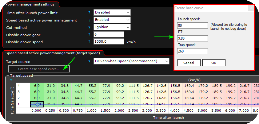
By clicking on the create base speed curve... button and enter data in the popup window, a base table can be created as a base to get you started.
Import a baseline

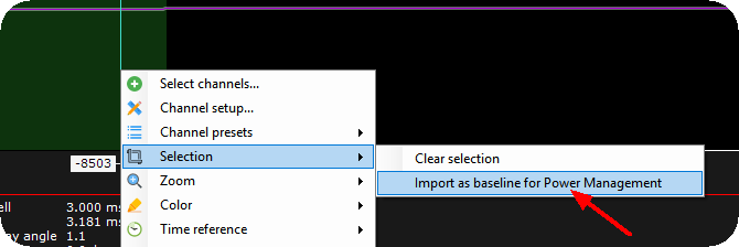
Open a logfile, select the area with SHIFT-key and left mouse press, the right click and select Selection --> import as baseline for Power Management, after the baseline has been imported, everything can be tuned from there.
Video example
MaxxECU Academy - Power Management
Power adder explained
