User PID Control – Overview
The User PID control system provides flexible, per-channel regulation of actuators such as boost solenoids, E-throttle, or VVT systems.
Each of the four available PID channels independently calculates a control output based on user-configured PID settings and real-time input values.
The control output (duty cycle) is computed using the standard PID formula with optional feed-forward and filtering:
Output = FF + (P × error) + (I × Sumoferrors) − (D × Delta error) ± Deadtime
•FF = Feedforward value (if enabled)
•P = Proportional gain
•I = Integral gain (scaled by time and limited)
•Sumoferrors = Accumulated error over time
•D = Derivative gain (with filtering)
•Delta error = Change in error since last cycle
•Deadtime = Small offset to compensate for slow solenoids
•Final output is limited between min Duty and max Duty.
Key features include
•Per-channel PID frequency and PWM frequency settings
•Optional feed-forward support
•Configurable integrator clamping using static or dynamic tables
•Multiple levels of derivative filtering
•Support for solenoid-specific behaviors like deadtime compensation
•Built-in test mode for calibration and troubleshooting
•This system allows fine-tuned and reliable control for a wide range of engine management functions.
Mostly used with servomotors and linear actuators wired to a MaxxECU H-bridge outputs for controlling active aero or similar.
User PID
Description
Name of the PID control output.
control enabled
This setting controls whether the PID regulator is active, and under what conditions.
•disabled - The PID controller is disabled. All internal accumulators (I, D, etc.) are reset to default.
•Test mode (set duty) - PID logic is bypassed. A fixed duty value is output directly.
•Enabled, always active - The PID controller is always active.
•Enabled, with enable input - With the enable input option, the digital input function User PID X enable control can be used to turn on the PID controller by any desired conditions.
test duty
The Test Duty setting defines a fixed output percentage used when the PID controller is in Test Mode. Instead of calculating PID output, the system forces the solenoid or output channel to this constant value.
controller settings
process variable
This is the measured process value. For example the position of an actuator.
This is normally an analog input calibrated for 0-100%, but this can be any values in the range of -3200.0 to 3200.0
direction
Defines how the PID output duty affects the process variable, that is whether increasing the control signal should increase or decrease the regulated value.
•Normal (increased duty --> increased process variable). - Use when the actuator affects the system proportionally, for example more valve opening results in higher pressure.
•Inverted (increased duty --> decreased process variable) - Use when the actuator affects the system inversely, for example more valve opening results in lower pressure.
mode
This setting controls how the PID controller's output is applied, depending on the type of actuator or control method used.
•Solenoid control - Default mode for PWM-controlled solenoids. Enables deadtime compensation, which adds/subtracts a small offset to overcome lag in solenoid response. Typical for boost control, idle valve, or similar PWM solenoids that benefit from deadtime adjustment.
•motor control - Motor control, no deadtime compensation is applied.
target value
target value table
The target value is the desired value that the PID controller tries to reach and maintain.
PWM output
pwm frequency
This setting defines the frequency (in Hz) of the PWM signal sent to the actuator (e.g., solenoid or valve). Must match the physical capabilities of the device (e.g., some solenoids respond poorly to too high or too low frequencies).
Solenoid dead time
The Solenoid Deadtime compensates for the mechanical delay in solenoid response, especially at low duty cycles. Most solenoids require a minimum pulse width before they begin to move or react. This setting adds or subtracts a small amount of extra duty cycle to overcome this delay. Ensures the solenoid begins reacting earlier and more consistently, improving control accuracy during low boost or spool-up phases.
How to set the solenoid dead time
Set this to a pulse width just below where the solenoids begins to flow.
This can be set by testing the solenoids set to a User PWM temporarily, set the frequency you want to use, and increase the duty cycle % to where the solenoid begins to flow. Then set the dead time value to: 10 * startflow% / frequency.
Example: If the frequency is 50Hz and the solenoid begins to flow at 24%: 10* 24 / 50 = 4.8ms, set the dead time around 10% below --> 4.3ms.
min duty
This setting defines the lowest allowed duty cycle that the PID controller can output. It acts as a safety and functional limit to ensure the PWM signal is strong enough to activate the solenoid or actuator.
Limits the PWM output duty to specified values. Negative duty is output on the "negative" PWM output.
PID controller with just one output uses 0-100% for example, while double-ended controllers can use -100% to 100%.
If the calculated PID output is below this threshold, it’s clipped to this minimum value (or zero, if the logic dictates so).
max duty
This setting defines the highest allowed duty cycle that the PID controller can output. It acts as an upper limit to protect solenoids or actuators from being overdriven.
Applies to both positive and negative outputs in systems using bidirectional control (e.g. -100% to +100%).
PID controller with just one output uses 0-100% for example, while double-ended controllers can use -100% to 100%.
Provides safety margin and tuning flexibility to avoid aggressive actuation and maintain stable system behavior.
Information
If dual PWM outputs are configured, the system can output negative duty. Positive duty (0–100%) is sent to the primary PWM output. Negative duty (−1 to −100%) is sent to the secondary (inverted) PWM output.
This allows control of dual-ended solenoids or valves with push-pull behavior.
In contrast, a single-output solenoid only uses 0–100%, and any negative PID result is clamped to zero. This dual-output design expands compatibility with various solenoid types and control strategies.
PID controller settings
PID frequency
Defines how often the PID control loop runs, measured in Hz (updates per second).
Sets the update rate for boost control logic (error calculation, PID response, solenoid output).
Affects how quickly the ECU reacts to boost changes.
This can be different from the PWM frequency. It should never be faster than the PWM frequency, but if the PWM frequency is high, it can be slower.
Note: 100-200Hz is good for most controllers.
PID GAINs
Specifies whether the P, I, and D gains use fixed values or dynamic tables.
•Fixed - Uses fixed P,I and D gain values. Simple setup for stable and predictable conditions.
•PID tables - Instead of fixed values, dynamic tables for P,I and D is available. Allows gain adjustments across load, RPM, or other axes for higher accuracy and adaptability.
Note: PID tables is only available on output 1 and 2.
P gain
The Proportional gain determines how strongly the controller reacts to the current error between the target and the process value.
A higher P gain increases reaction speed and responsiveness.
Too high can cause overshoot or instability.
Too low makes the system slow or unresponsive.
Use P gain to set how aggressively the controller should correct the error on each cycle.
I gain
The Integral gain controls how the PID controller accumulates and corrects long-term steady-state error over time.
The error is multiplied by I gain and accumulated every cycle. Optional I limiters can constrain the total integral to prevent windup.
A higher I gain improves accuracy but can cause oscillation or slow response if too aggressive.
Resets to zero when controller is disabled.
If error is small but consistent, the I term builds up gradually and increases the duty output to eliminate the offset.
Use I gain to fine-tune how strongly and how quickly long-term errors are corrected.
D gain
The Derivative gain reacts to how quickly the error is changing over time, helping to dampen the system response and reduce overshoot.
The result is subtracted from the output to slow down fast error changes.
The change in error ( delta error) is smoothed using an exponential filter.
Damping effect: reduces overshoot and instability caused by fast-changing signals.
A higher D gain makes the system more resistant to sudden changes but may slow the response too much.
Use D gain to smooth out sharp movements and improve control during fast transitions or ramping.
D filter
This setting defines how much smoothing is applied to the derivative (D) term, which reacts to how fast the error is changing.
•No filter - Basic exponential smoothing with fixed alpha. Less stable and not recommended for most use cases.
•Low (fast processes) - Strong filtering (smoother response). Best for noisy signals or when D-term causes oscillation.
•medium - Balanced filtering. Good general-purpose option.
•high (slow processes) - Light filtering (more responsive). Best when fast response is needed and the signal is clean.
see, PID control.
I limiter
This parameter controls how the integral (I) term is limited in the PID controller. It determines which strategy is used to prevent integral wind-up.
•default +/- 50% - Applies the same limit to both positive and negative accumulation.Simple and safe for most use cases
•table +/- - Uses a 3D I Limiter Table to scale the limit dynamically. Applies limit symmetrically, allowing both positive and negative integral values. Ideal when dynamic conditions (e.g. RPM, boost) affect how much correction is safe.
•table only + - Same calculation as table +/-, but limits only the positive side of the I term. Useful for systems where negative integral values are not needed or could cause undesired behavior.
I limiter table
The I-Limiter can be used to limit the integer (I) term to prevent windup, or to allow more aggressive I tuning.
Set the axis to the PID error RT-value, and tune for lower allowed errors with large errors, and larger values close to the target. This helps preventing overshoot, while still allowing the I term to hold the position firmly.
FeeD-forward enabled
Feed-forward adds a predefined duty directly to the PID output based on system input, improving response time and reducing reliance on feedback. Useful for overcoming known forces like spring pressure in actuators.
•Disabled - no feed-forward applied.
•Enabled - The result is added before PID terms (P, I, D). Provides an immediate output response even before error builds up. Reduces the work the PID controller must do, especially the integral term. Ideal for predictable systems, e.g., boost control where duty vs. target is known.
Example
Example of controlling an rear spoiler (active aero) using MaxxECU RACE H-bridge outputs.
(in this example, we assume a servomotor is wired to MaxxECU motor outputs and are properly working).
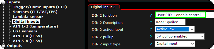
1. Connect a switch to an available digital input to activate the active aero. You can also trigger this input using other sources, such as vehicle speed (via internal output system conditions), MDash, or a CAN keypad.
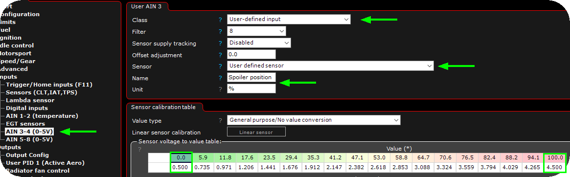
2. A position sensor must be wired and calibrated. In this example, a linear position sensor is used and scaled to represent 0–100% spoiler position based on its voltage output. For reference, 50% corresponds to the horizontal (neutral) spoiler position.

3. Enable the User PID positive and/or the User PID negative.
Note: the User PID function does work on all outputs, but make sure the electrical peripheral wired is matching the MaxxECU electrical output features.
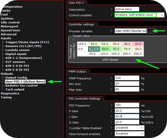
4. In this example, the rear spoiler position is controlled using a target table (TPS vs vehicle speed), allowing it to adjust for increased downforce at higher speeds.
Note: Before real-world testing, ensure all PWM frequency and PID settings are properly configured to match the actuator characteristics. This is crucial for correct and smooth spoiler movement.