The MaxxECU RACE adapter for Audi ME 7.1 ECUs.
(for information on the old MaxxECU V1 + E-Throttle module adapter, click here)
Note: Can only be used with MaxxECU RACE.
Vehicle cover list
Vehicle |
Engine code |
Year |
LSU sensor |
Note |
Audi S4 B5 2.7 biturbo |
AGB, AZB |
1998 - 2002 |
External sensor needed |
Only uses one WBO sensor |
Audi RS4 2.7 biturbo |
AZR |
2001 |
External sensor needed |
Only uses one WBO sensor |
Golf R32 |
BDE |
1997 - 2003 |
Uses stock LSU 4.2 sensor |
Not available yet!! |
Note: No auto transmission (manual gearbox only) support on any model!
Note: Not all ME 7.1 have CAN pinned in the ODB connector for ODBII functionality.
EXTREMELY IMPORTANT NOTE: You MUST remove ALL stock narrow bands lambda sensors, since they WILL interfere with the LSU 4.2 sensor and cause wrong lambda readings.
Control options
Options |
OEM ECU PIN |
MaxxECU IO |
RACE |
Note |
VVT solenoid |
115 |
GPO 1 |
Yes |
|
Check engine light |
48 |
GPO 2 + Audi ME 7.5 CAN |
Yes |
|
Boost solenoid (OEM) |
104 |
GPO 4 |
Yes |
Only on turbo engines |
Variable intake valve |
121 |
GPO 4 |
Yes |
Only on Golf R32. Can be used to control the variable intake, or for boosted applications the boost solenoid (requires a solenoid to be wired to the valve solenoid connector) |
Fuel pump relay |
65 |
GPO 5 |
Yes |
|
VVT exhaust solenoid |
120 |
GPO 6 |
Yes |
Parallel connected to extra 16-pin connector also if not used. |
Tachometer |
37 |
GPO 8 + Audi ME 7.5 CAN |
Yes |
|
E-Throttle |
117/118 |
GPO 11/12 |
Yes |
|
Sequential injection |
|
INJ 1 - 6 |
Yes |
|
IAC cutoff valve |
9 |
INJ 7 |
Yes |
|
EVAP |
64 |
INJ 8 |
Yes |
|
Sequential ignition |
|
IGN 1 - 6 |
Yes |
|
Knock sensors (OEM) |
106, 107 |
KNOCK1, KNOCK2 |
Yes |
|
Secondary air pump |
44,46 |
- |
|
|
Intake air temperature sensor |
|
IAT |
Yes |
Paralell connected with 2-pin extra connector |
Coolant temperature sensor |
|
CLT |
Yes |
|
Clutch switch |
39 |
AIN 1 |
YES |
|
Brake pedal |
56 |
AIN 2 |
YES |
|
Vehicle speed (VSS) |
54 |
DIN 1 |
Yes |
Also from CAN, Audi ME 7.5 CAN |
EPC light |
- |
CAN only! |
|
|
Instrument cluster/ABS |
- |
CAN only! |
|
|
Fuel consumption |
|
|
|
|
Cruise control |
|
|
|
|
Bluetooth (MDash) |
|
|
Yes |
|
EGT option |
|
|
Yes, direct |
6 EGT direct in harness |
OEM EGT-sensors |
|
Note: On US models Motor + and Motor- is switched, our base maps are made for the EU market, so a manual switch of the outputs in MTune must be done, Outputs --> Output config.
Plugin adapter description
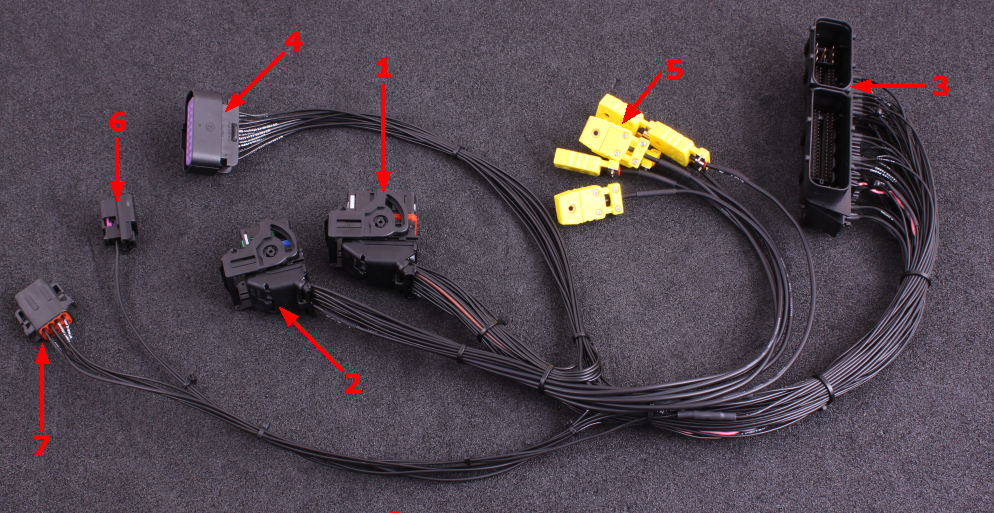
1 |
MaxxECU RACE CMC connector 1 |
2 |
MaxxECU RACE CMC connector 2 |
3 |
Vehicle harness adapter |
4 |
16-pin extra connector |
5 |
MaxxECU built-in EGT (1-6) mini-k connectors |
6 |
2-pin extra connector for external intake temperature sensor (IAT). Sensor/cable not included |
7 |
8-pin DTM connector (for external WBO). Cable and sensor included |
ECU location and installation
Stock ECU is located in engine bay on driver side.
1.Remove the plastic guard where the ECU is located.
2.Disconnect battery from vehicle.
3.Remove and disconnect stock ECU from vehicle harness.
4.Install MaxxECU adapter harness.
5.Route the included MaxxECU MAP-sensor hose to the intake manifold and connect into the MaxxECU.
6.If your vehicle have LSU sensor(s) mounted from factory (see vehicle cover list on the top if this page), skip the next step.
7.Install the included lambda sensor in exhaust and route the wide band lambda cable to the MaxxECU unit and secure the DTM 8 connector.
8.Your MaxxECU unit is preloaded with the correct basemap for your vehicle.
9.We assume you have read the included Quick start guide, and now it's time for the engine start.
Note: MaxxECU RACE plugin ECU kit, might not fit into the standard plastic ECU box. Make sure to mount the ECU away from heat or water!
Most people do route the adapter harness inside the car, and only let the adapter harness and stock ECU connectors be left in the plastic box in engine bay.
8-pin extra connector (WBO)
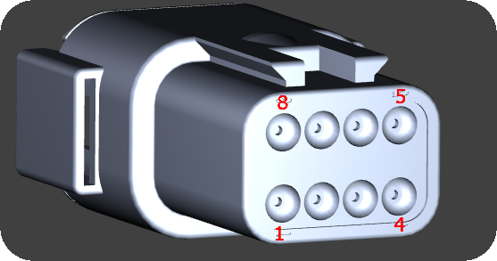
Seen from the wire side of the pre-wired connector.
Pin |
Description |
1 |
Lambda VREF |
2 |
Lambda VS |
3 |
Lambda Shield (not always used) |
4 |
Lambda IP |
5 |
Lambda RCAL |
6 |
- |
7 |
Lambda +12V |
8 |
Lambda Heater- |
If you vehicle is equipped with a stock LSU 4.2 sensor, do not connect a external here, see vehicle cover list above.
16-pin extra connector
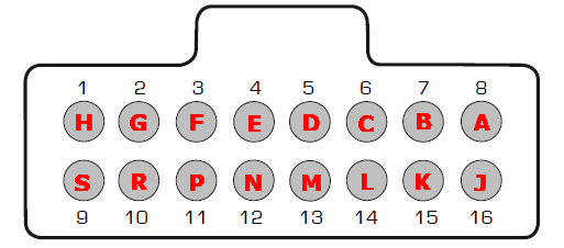
Note: Pinout is from the wire side of the included 16-pin connector.
Pin |
Description |
Usage |
Note |
1 (H) |
+5V sensor supply |
|
|
2 (G) |
Sensor GND |
|
|
3 (F) |
TPS AIN |
|
|
4 (E) |
AIN 4 |
|
|
5 (D) |
DIN/VR 4 |
|
|
6 (C) |
DIN/VR 5 |
|
|
7 (B) |
GPO 6 |
Also parallel connected to VVT exhaust valve (if your vehicle has one) |
|
8 (A) |
GPO 7 / DIN 3 |
|
|
9 (S) |
|
|
|
10 (R) |
|
|
|
11 (P) |
|
||
12 (N) |
+12V |
Output at ignition on |
|
13 (M) |
Engine GND |
|
|
14 (L) |
GPO 3 |
||
15 (K) |
DIN 2 |
||
16 (J) |
AIN 3 |
See also
Example wirings of extra input and output