BMW DCT related links
•BMW DCT BIG HOWTO. <-- READ this guide, please, just do it before asking questions already covered.
•BMW DCT TCU firmware flashing.
•DCT Realtime Data description.
How does the BMW TCU torque control works
(even more information here for the gecky customers...)
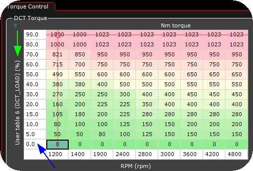
•All torque values transmitted to the TCU is between -1024 and 1023Nm.
•The transmitted torque value has a direct relation to the DCT clutch pressures, but be aware, DO NOT send to much torque to the TCU on lower loads (since that will not give you a smooth shift transition).
•If you engine produces max 600Nm on the dyno, there is no reason to send 1000Nm if you do not want to make sure you have maximum clutch pressure, always keep an eye on the RealTime Data Value clutch slip.
•The standard torque table values will probably work for most setup, but might require a little bit of tweaking.
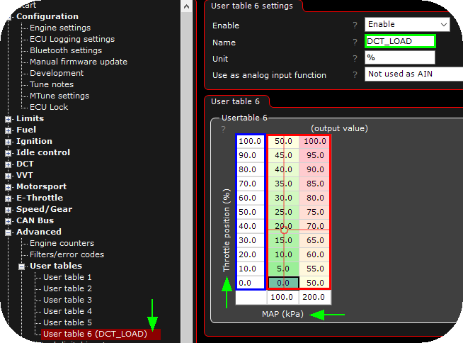
•The torque strategy transmitted to the TCU is HIGHLY advanced, but we have tried to simplify everything to make it easier for you to tune in, therefore, only one torque value is available to be tuned.
•The shifting operation uses the pedal position (drivers torque choice) and the SPORT (GEN1 335) button / Drivelogic mode 1-6 (GEN1 M3) / Drivelogic mode 1-3 (GEN2) as a simplified and automatic shift hardness setting. GEN1 Mode 6 / GEN2 Mode 3 + full throttle = maximum shift hardness
Launch torque control
clutchslip mode during launch
When enabled, we will not transmit the brake signal to the TCU, and you can use this method to "build boost against the clutch", over a VERY short period of time before you eventually will burn them. <-- DO NOT blame us if you end up with damaged clutches, you have been warned.

Example usage of the torque during launch table to build a boost towards the clutch.
Torque during launch table
Torque control table when the digital input launch control is active. This is the torque (in Nm) which is transmitted to the TCU during launch. As soon as the launch button is released, the regular torque control tables is used.
Note: A value between -600 and -1024 is necessary to not burn the clutches during the building of boost.
burnout torque control
Burnout rpm table
To be able to do a burnout with the DCT gearbox, you might need to activate the digital input DCT clutchkick/burnout mode to force a negative torque value to be sent to the TCU during engine rev-up (no clutch engagement), when exceeding this RPM value, MaxxECU rapidly transmitting FULL torque to simulate a clutchkick to make the wheel spin and make sure no clutch slippage during the burnout.
torque value before burnout RPM
The reported torque (Nm) until burnout RPM is reached (WHILE the digital input DCT clutchkick/burnout mode is active). (default -500Nm).
used toRQUE mode after burnout RPM reached
•use max torque available - Uses the max value available in this configuration, max value set in DCT Settings, max reported torque value (min/max) when the burnout input is active.
•Use regular torque table - Uses the regular torque table values when the burnout input is active.
Possible to make a burnout with MaxxECU controlling the DCT gearbox? Yes...
Torque control
DO NOT TRANSMIT MORE TORQUE THAN YOUR ENGINE DELIVERS, YOU WILL GET TCU ADAPTION ERROR CODES AND WEIRD SHIFTS
DCT torque
This is the main torque table, transmitting the torque value to the TCU, as written above, the transmitted torque value has a direct relation to clutch pressures.
Example torque values:
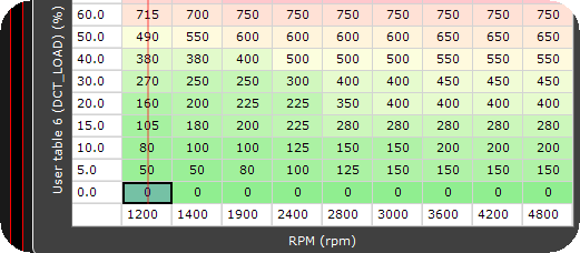
•Idle: -100 to 50Nm, keep it as low as possible to prevent vehicle from moving without having the brake pedal engaged, to high number on idle will give TCU error codes.
•Light load: try to keep the value as low as possible, without having to much clutch slip.
•Middle load: Same here, do not send to much torque, it will give you "rough" shifting operation, but must be high enough to prevent too much clutch slippage.
•High load: Be sure not to send to much torque before the engine actually has almost the same torque load.
Note: If the transmitted torque value differs to much from the calculated clutch torque (inside the TCU), a DCT error code will be thrown and shifting operations will go sideways.
DCT reported throttle angle
Table used to alter the reported throttle angle to the DCT TCU. Can be used to adjust the shift points in automode.
Note: Not used with the default shifting strategy.
DCT torque correction
The torque correction table, mostly used during launch to make a small clutch slip to prevent wheels from slipping.
100% = no correction (normal and standard value) = uses the main torque table.
Note: Be careful here, especially with a lot of power, not to let the DCT clutches slip for a longer period of time, see DCT hardware upgrade.
DCT shifting options
MaxxECU DCT shiftings
DCT UP shift
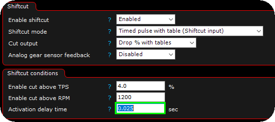
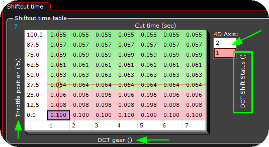
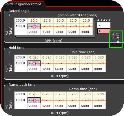
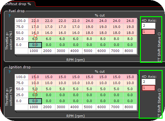
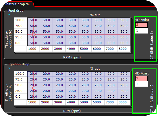
Shiftcut on UP shift is not "needed", it works flawlessly without any kind of cut, but might increase the ware of your clutches, but it shifts fine without....your decision.
Note: The shiftcut event is ALWAYS triggered from the DCT control to the shiftcut system during an up shift event, regardless of Drivelogic mode, engine load or pedal position, it is up to the Shiftcut settings to decide whether to do a shiftcut or not.
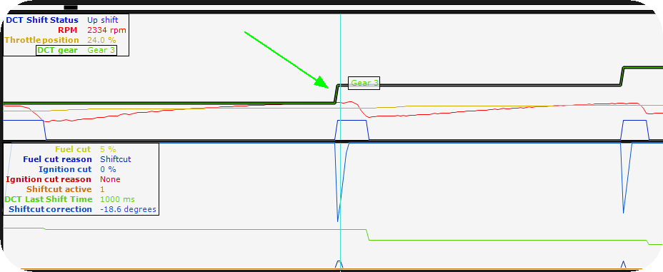
Example interesting data during an DCT up shift operation, with shiftcut feature activated.
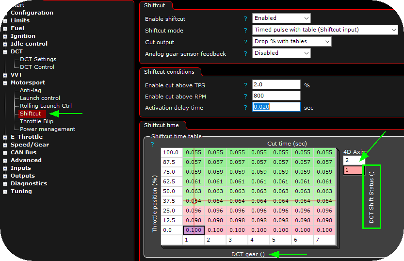
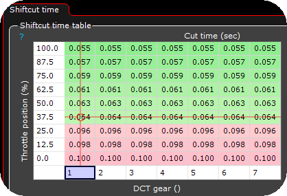
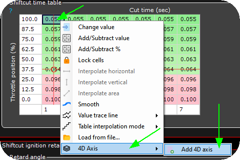
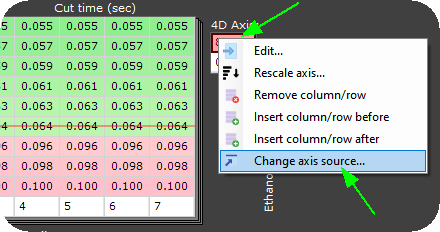
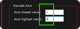
Example shiftcut setting, here different settings for up and down shifts using the True 4D feature of MaxxECU. See DCT shifting options for all shifting options.
How to DCT downshift (GEN1 drivelogic mode 1,2,3 / GEN2 drivelogic mode 1)
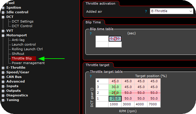
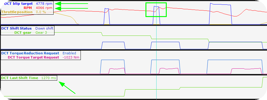
The TCU sends an downshift event to MaxxECU (via CAN) which internally activates the Throttle blip feature, which is a required to successfully downshift in this mode.
Downshift with pedal below 2%.
Just press the downshift, and it will downshift :)
Note: The shiftcut event is NOT triggered below 2% pedal in ANY drivelogic mode.
DCT downshift with pedal over 2%.
Over 2% pedal, the torque table is used, and in some cases it MIGHT need to use the shiftcut feature to reduce engine power during a downshift.
Note: The shiftcut event IS always triggered over 2% pedal position in ANY drivelogic mode.
How to DCT downshift and throttle blip (GEN1 drivelogic mode 4,5,6 / SPORT MODE / GEN2 drivelogic 3)
Downshift with pedal below 2% (blip is required)
The TCU sends an downshift event to MaxxECU (via CAN) which internally activates the Throttle blip feature, which is a required to successfully downshift in this mode.
Note: The shiftcut event is NOT triggered below 2% pedal in ANY drivelogic mode.
DCT downshift with pedal over 2%.
Over 2% pedal, the torque table is used, and in some cases it MIGHT need to use the shiftcut feature to reduce engine power during a downshift.
Note: The shiftcut event IS always triggered over 2% pedal position in ANY drivelogic mode.
How to DCT downshift and throttle blip (GEN2) new 2025 improved strategy
The TCU sends an downshift event to MaxxECU (via CAN) which internally activates the Throttle blip feature, which is a required to successfully downshift in this mode.
Uses a user-tunable PID loop to command throttle targets so engine speed tracks the blip-RPM setpoint in closed-loop, enabling quicker, more stable downshifts.
Prerequisite: the E-throttle must be accurately calibrated and responsive.
Use together with the 2025 shift strategy.
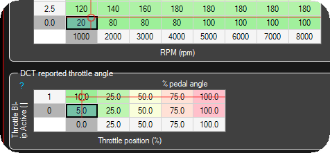
1. Ensure a proper engine torque table. Giving the system some extra throttle when on blip, might improve the downshift speed.

2. Create a user PID function in the Outputs -> Output config.
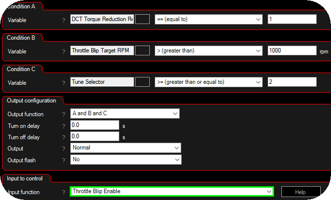
3. Create an internal output which triggers the throttle blip enable digital input, based on the above conditions. Advanced --> Internal outputs.
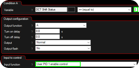
4. Create another internal output which enables the user pid 1 enable control feature when the DCT shift status is 2 (downshift).

5. Enable the throttle blip using the enable signal.
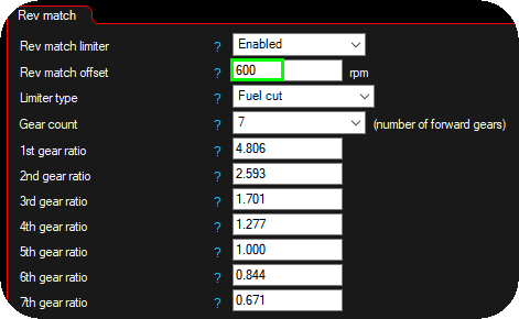
6. Optional rev match limiter with an rev match offset, to prevent too much overshoot as a protection.
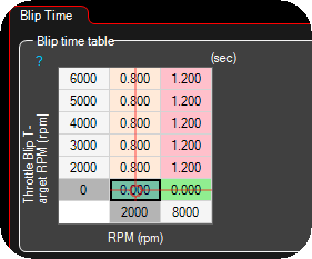
7. Max allowed blip times.

8. Set the throttle target to follow the user pid duty between 0 and 70%.
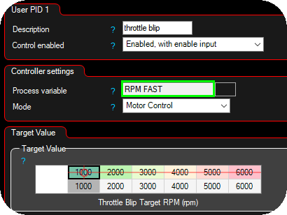
9. User PID 1 settings, use the RPM FAST as the process value and set a 1:1 target value conversion between the throttle blip target rpm and the output target rpm.
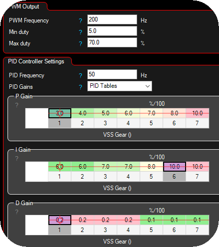
10. Setup basic User PID values., Most likely you need PID Gains using PID tables, example values to begin with.
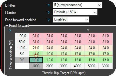
11. Set the Feed-Forward (FF) table first. It must predict the throttle command needed to reach the blip RPM setpoint so the PID only trims small residuals. If FF is off, the user-PID will react late/slow.
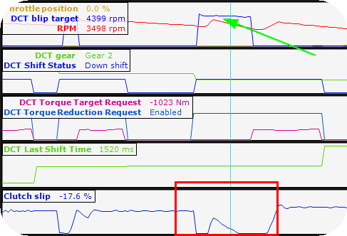
12. Adjust parameters to that the engine RPM is as close to the throttle blip target rpm as possible. Use the DCT Torque Request Helper for suggestions.
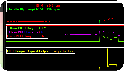
Small overshoot.
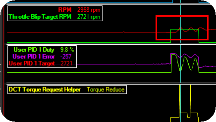
Oscillating engine RPM, PID parameters needs to be cooled down.
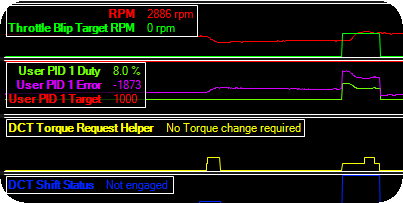
Slowly progressing to maintain a stable engine rpm during downshift, please watch the DCT shift status, it will be shorter and shorter when you are getting in the right direction.

