BMW DCT related links
•BMW DCT BIG HOWTO. <-- READ this guide, please, just do it before asking questions already covered.
•BMW DCT TCU firmware flashing.
•DCT Realtime Data description.
DCT settings
Gearbox type
Specifies the gearbox type and the TCU (Transmission Control Unit) used. The actual TCU version is the most important thing here.
•GEN1 GS7D36SG DCT (BMW 335 TCU) - OE TCU firmware seems to work.
•GEN1 GS7D36SG DCT (BMW M3 TCU, GTS fw) - GTS based firmware is required.
•GEN2 GS7D36SG DCT (BMW M4 TCU, custom fw) - Custom TCU firmware is required, available using the xHP app, see BMW DCT TCU firmware flashing.
Shifter type
Specifies which gear shifter is used.
•OEM BMW shifter - with this option, stock shifter, SPORT button (BMW 335) or drivelogic button (BMW M3) must be present and communicate directly with the TCU.
•Shifter emulation - with this option, digital inputs are used to "simulate" the OE shifter, DCT shifter emulation.
TCU speed source
The vehicle speed source we report to the TCU.
•Vehicle speed (using TCU OEM rear end diff ratio) - Can ONLY be used when your rear end diff ratio is2.65 (GEN1 335), 3.15 (GEN1 M3) and 3.46 (GEN2 M4).
•Undriven wheel speed (rear end diff ratio setting - corr) - Uses the correct vehicle speed (undriven) and your rear end diff ratio (and using the below Speed gear ratio correction (to TCU) correction) to calculate a correct TCU speed value.
•Driven wheel speed (rear end diff ratio setting - corr) - Uses the correct vehicle speed (driven) and your rear end diff ratio (and using the below Speed gear ratio correction (to TCU) correction) to calculate a correct TCU speed value.
•Undriven & Driven wheel speeds (rear end diff ratio setting - corr) - Uses the correct vehicle speed (undriven and driven) and your rear end diff ratio (and using the below Speed gear ratio correction (to TCU) correction) to calculate a correct TCU speed value.
•Dyno Mode (using rpm & current gear) - corr - Dyno mode, mainly for customers mounted a front wheel speed sensor but heading to a RWD dyno where front wheel not moving. <-- Experimental feature, less perfect shift operation will occur.
Note: The 4 speed values we send to the TCU has a direct relation to shifting points, performance and clutch slippage during shift operations. Therefore the vehicle speed inside MaxxECU must be very precise and accurate, otherwise this will not work.
Speed gear ratio correction (to TCU)
Used to adjust the reported speed to the TCU.
clutch kick time
Specifies the clutch kick time.
•switch input (while input active) - Activates the clutch kick feature (releases the pressure on the clutch in gearbox) while the digital input DCT clutchkick/burnout mode is active.
NOTE: Experimental feature for testings only, you might wanna combine this with a secondary rev limit.
Max reported torque value (min/max)
Modifies the reported (and transmitted) torque value to the TCU with this value in both directions. For example, "800" will limit torque values between -800Nm and 800Nm.
DCT shifting options
shift strategy
Which shifting strategy to use.
Note: The shiftcut signal is always triggered upon an UP or DOWN shift event (signaled from the TCU), you need to set them up in MaxxECU Shiftcut settings.
DCT downshift requires everything to be correctly set and a Throttle blip function is required.
Shiftcut source
Note: GEN2 protocol does not use this setting.
Specifies which function to trigger the MaxxECU Shiftcut input.
•torque request from tcu - Uses the torque request input to trigger the internal shiftcut input (preferable use this method).
•shift signal from tcu (recommended) - Uses the shift input (which happends a few milliseconds before the above actual torque request signal) as shiftcut input trigger.
Note: The reason why we have this option, is because we have seen issues with the above Torque request from TCU signal from the TCU in some application (for an unknown reason).
Blip delay
The TCU sends a "blip request" to the MaxxECU, this setting can delay the blip function to make sure the clutches disengages before the engine is revved up.
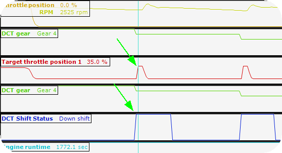
Example blip delay of 60ms to make the DCT clutches to be release before Throttle blip activation occurs.
DCT protection
clutch slip engine cut
Specifies whether to protect the gearbox clutches against clutch slippage, it is HIGHLY recommended to have this enabled. It uses the below settings for activation of engine cut, see DCT hardware upgrade for example of damaged clutches if it slip too much...
max clutch slip on load
Specifies the maximum allowed clutch slippage when under "load" (VSS > 30km/h, TPS > 15%, RPM > 2000).
Note: we dont pay attention to the slippage during launch and 1000ms after launch is deactivated.
max clutch slip during shifting
During DCT shiftings, we cant calculate the slip rate accurately, therefore during shifting we allow a higher slippage to prevent unnecessary engine cuts during shifting's.
DCT Warnings
max allowed upshift time (low load)
Specifies the maximum allowed shifting time (ms) during low load. Below 30% TPS.
max allowed upshift time (normal load)
Specifies the maximum allowed shifting time (ms) during normal load. 30 - 80% TPS.
max allowed upshift time (high load)
Specifies the maximum allowed shifting time (ms) during high load. Over 80% TPS
max allowed downshift time
Specifies the maximum allowed shifting time (ms) during a downshift.
MaxxECU DCT shiftings
DCT UP shift
Shiftcut on UP shift is not "needed", it works flawlessly without any kind of cut, but might increase the ware of your clutches, but it shifts fine without....your decision.
Note: The shiftcut event is ALWAYS triggered from the DCT control to the shiftcut system during an up shift event, regardless of Drivelogic mode, engine load or pedal position, it is up to the Shiftcut settings to decide whether to do a shiftcut or not.
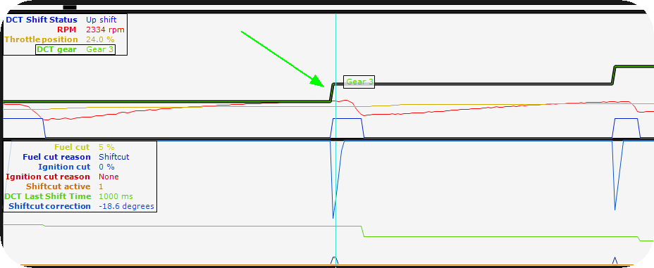
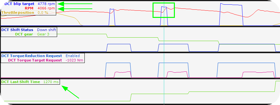
Example interesting data during an DCT up shift operation, with shiftcut feature activated.
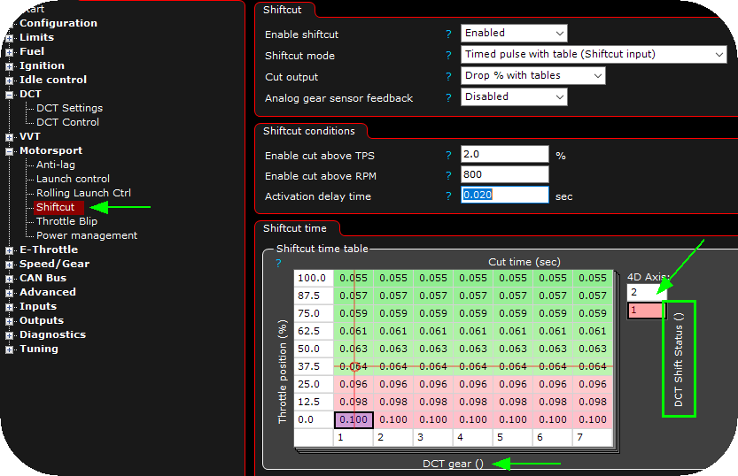
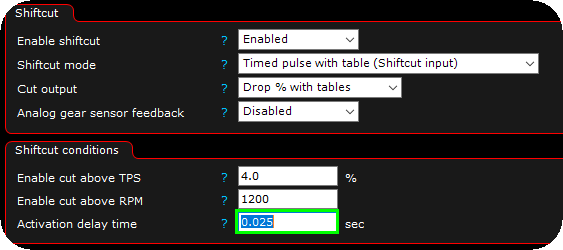
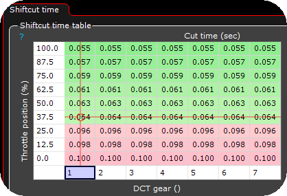
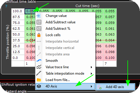
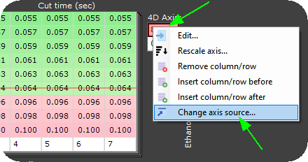
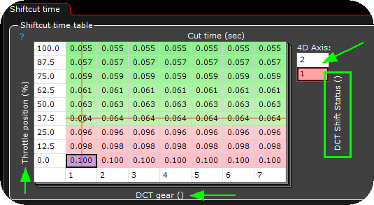
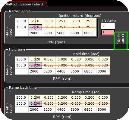
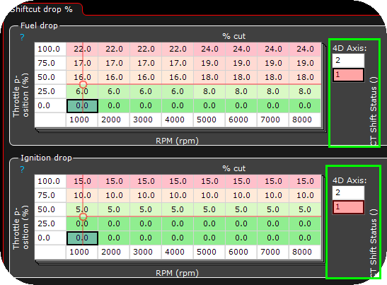
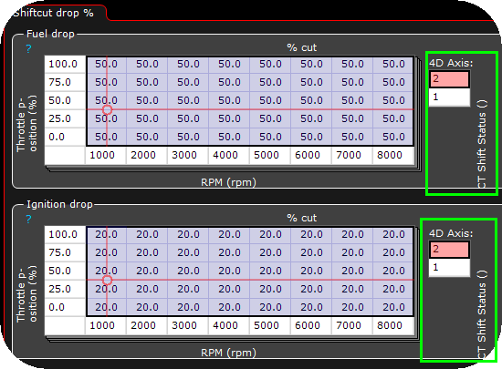
Example shiftcut setting, here different settings for up and down shifts using the True 4D feature of MaxxECU. See DCT shifting options for all shifting options.
How to DCT downshift (GEN1 drivelogic mode 1,2,3 / GEN2 drivelogic mode 1)
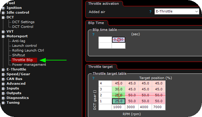
The TCU sends an downshift event to MaxxECU (via CAN) which internally activates the Throttle blip feature, which is a required to successfully downshift in this mode.
Downshift with pedal below 2%.
Just press the downshift, and it will downshift :)
Note: The shiftcut event is NOT triggered below 2% pedal in ANY drivelogic mode.
DCT downshift with pedal over 2%.
Over 2% pedal, the torque table is used, and in some cases it MIGHT need to use the shiftcut feature to reduce engine power during a downshift.
Note: The shiftcut event IS always triggered over 2% pedal position in ANY drivelogic mode.
How to DCT downshift and throttle blip (GEN1 drivelogic mode 4,5,6 / SPORT MODE / GEN2 drivelogic 3)
Downshift with pedal below 2% (blip is required)
The TCU sends an downshift event to MaxxECU (via CAN) which internally activates the Throttle blip feature, which is a required to successfully downshift in this mode.
Note: The shiftcut event is NOT triggered below 2% pedal in ANY drivelogic mode.
DCT downshift with pedal over 2%.
Over 2% pedal, the torque table is used, and in some cases it MIGHT need to use the shiftcut feature to reduce engine power during a downshift.
Note: The shiftcut event IS always triggered over 2% pedal position in ANY drivelogic mode.
How to DCT downshift and throttle blip (GEN2) new 2025 improved strategy
The TCU sends an downshift event to MaxxECU (via CAN) which internally activates the Throttle blip feature, which is a required to successfully downshift in this mode.
Uses a user-tunable PID loop to command throttle targets so engine speed tracks the blip-RPM setpoint in closed-loop, enabling quicker, more stable downshifts.
Prerequisite: the E-throttle must be accurately calibrated and responsive.
Use together with the 2025 shift strategy.
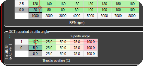
1. Ensure a proper engine torque table. Giving the system some extra throttle when on blip, might improve the downshift speed.

2. Create a user PID function in the Outputs -> Output config.
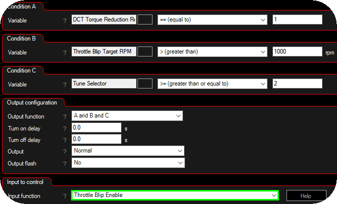
3. Create an internal output which triggers the throttle blip enable digital input, based on the above conditions. Advanced --> Internal outputs.
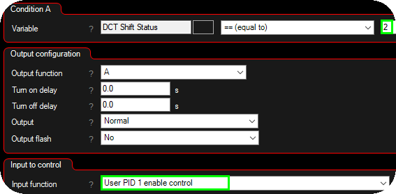
4. Create another internal output which enables the user pid 1 enable control feature when the DCT shift status is 2 (downshift).

5. Enable the throttle blip using the enable signal.
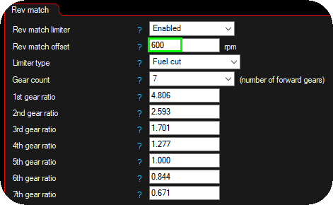
6. Optional rev match limiter with an rev match offset, to prevent too much overshoot as a protection.
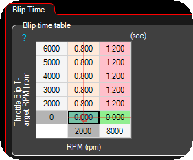
7. Max allowed blip times.

8. Set the throttle target to follow the user pid duty between 0 and 70%.
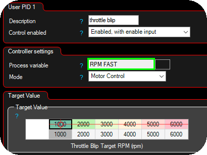
9. User PID 1 settings, use the RPM FAST as the process value and set a 1:1 target value conversion between the throttle blip target rpm and the output target rpm.
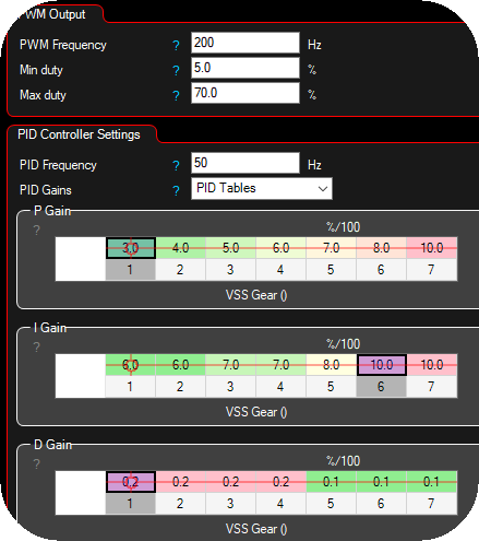
10. Setup basic User PID values., Most likely you need PID Gains using PID tables, example values to begin with.
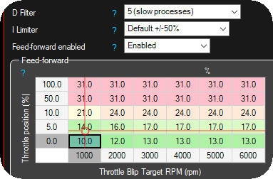
11. Set the Feed-Forward (FF) table first. It must predict the throttle command needed to reach the blip RPM setpoint so the PID only trims small residuals. If FF is off, the user-PID will react late/slow.
12. Adjust parameters to that the engine RPM is as close to the throttle blip target rpm as possible. Use the DCT Torque Request Helper for suggestions.
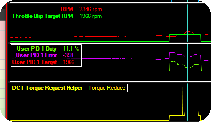
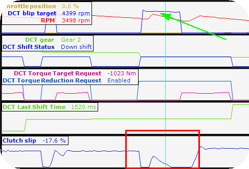
Small overshoot.
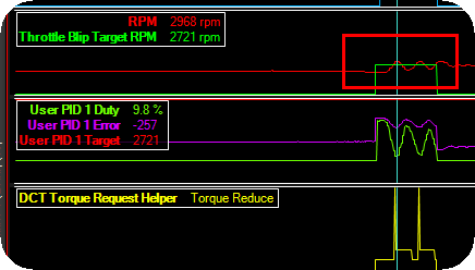
Oscillating engine RPM, PID parameters needs to be cooled down.
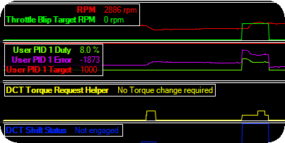
Slowly progressing to maintain a stable engine rpm during downshift, please watch the DCT shift status, it will be shorter and shorter when you are getting in the right direction.
TCU handling
TCU diagnostic requests
When enabled, MaxxECU are requesting TCU diagnostic values to get individual clutch pressures, calculated torque and line pressure.
Note: INPA cannot communicate with the TCU while this is enabled.
Reset TCU adaptations
This button resets:
•Adaptation values of clutch torque characteristic K1.
•Adaptation values of clutch torque characteristic K2.
•Adaptation values for DRM.
•Adaptation values of the semi-slip for gears 1-7.
Note: we are NOT resetting: Adaptation values Kisspoint K1/K2.


