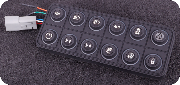
One of the CAN keypads retained by MaxxECU, with CAN integration. It is manufactured by Blinkmarine in Italy and works over J1939 CAN protocol.
Note, we also support the Grayhill/motec 15-key keypad on the PDM side, see Keypad settings.
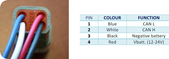
Blink Marine 4-pin DTM connector pinout.
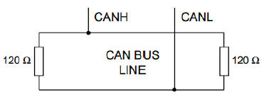
If you are wiring the CAN keypads to a MaxxECU PRO CAN2 (which is not terminated) you need to do this, otherwise you DO NOT NEED this.
Example wiring
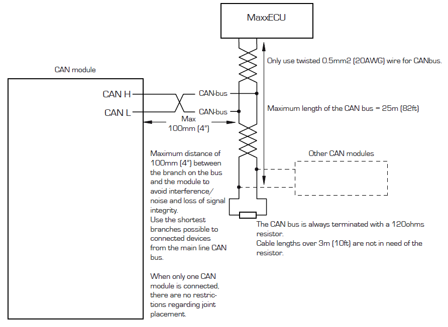
Example of CAN wiring.
Move on to CAN Keypad setup.

One of the CAN keypads retained by MaxxECU, with CAN integration. It is manufactured by Blinkmarine in Italy and works over J1939 CAN protocol.
keypad setup
bus baudrate
Sets the keypad baudrate.
•250kbit.
•500kbit (MaxxECU default).
backlight color
Sets the keypad backlight color.
•OFF.
•white.
•Amber.
•Yellow/Green.
default brightness
Sets the default LED indicators brightness level, 0 (min) to 63(max).
startup led show
Activates a certain keypad startup indication.
•OFF.
•LED show.
•FLASH.
keypad protocol setup
keypad protocol
Sets the keypad CAN protocol.
•J1939 - Used by MaxxECU.
•CANOpen.
Note: Keypads bought from MaxxECU or its resellers has them pre programmed with the J1939 protocol from factory.
Current canopen id
The current CANOpen ID used (default 0x15).

By pressing the above button, the connected keypad will be reprogrammed to the selected CAN protocol.
How to change a Blink Marine keypad from CANOpen to J1939 protocol.
1. Disconnect any PDM from the CAN bus (temporarily remove the 2 CAN pins from the PDM connector).
2. Change the MaxxECU "CAN 1/2 Bitrate" (on the "CAN settings" page) to match what the keypad currently uses (125kbit is the CANopen default, but it might also be higher). Dont forget to restart the MaxxECU after each CAN bus baudrate change.
3. Use the built-in CAN Analyzer or an external CAN analyzer to look for new CAN ID messages on the bus, which indicates there is something on the bus.
4. Under Keypad Setup, set protocol to J1939 and click Write to keypad. If the keypad accepts the command it will flash all LEDs. If it doesn't, try a different bitrate (restart the ECU every time you change the bitrate).
5. Now the Keypad is in J1939 mode. But the default bitrate in J1939 is 250kbit. MaxxECU uses 500kbit as default.
6. To change this: Change the MaxxECU "CAN 1/2 Bitrate" to 250kbit to match the Keypad. Restart the ECU.
7. On the Keypad setup page, change the keypad bitrate to 500kbit and write to the keypad.
8. Change the MaxxECU "CAN 1/2 Bitrate" to 500kbit, connect the PDM again, and restart. Now the keypad, ECU and PDM can communicate with the correct bitrate and protocols.
Example usage
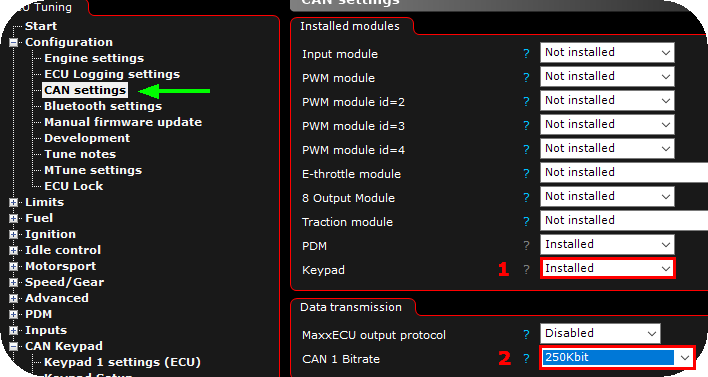
1. Enable the Keypad module in CAN settings.
2. Change MaxxECU CAN bitrate to 250Kbit (default 500Kbit) since the CAN keypads as default communicates at 250Kbit and we must match this during the initial CAN keypad programming. <-- DO NOT FORGET TO RESTART MAXXECU AFTER CHANGING CAN BITRATE!!!

3. Change the CAN keypad bus rate to 500kbit, select a suitable backlight color and press Write to Keypad button.
Note: This will reprogram the CAN keypad to use the higher CAN bus speed of 500Kbit, and right now it can't communicate with the MaxxECU since the difference in CAN speed.

4. Change back to MaxxECU default 500Kbit CAN baudrate. <-- DO NOT FORGET TO RESTART MAXXECU AFTER CHANGING CAN BITRATE!!!
If you have followed the above instructions properly, you now have a working CAN keypad in your MaxxECU setup.
Change keypad backlight color

You can anytime change the CAN keypad backlight color, but make sure you do not change the Bus baudrate setting!
keypad settings
Keypad
Select the CAN keypad you have installed.
Note: Currently we support the CAN PRO keypads, 4, 6, 8 and 12 key from Blink Marine.
The below is only available for PDM keypads.
backlight control
•Always on - The backlight is always on, programmed at Keypad setup.
•on/off with ignition on (no off delay) - The backlight is turned off when ignition key is OFF.
•on/off with ignition on (1 min off delay) - The backlight is turned off after 1 minute when an ignition key OFF event is detected.
•on/off with ignition on (5 min off delay) - The backlight is turned off after 5 minutes when an ignition key OFF event is detected.
backlight level, lights off
Specifies the background light level when lights is OFF.
backlight level, lights on
Specifies the background light level when lights is ON.
Note: 0-63, where 63 is the brightest, listens to the digital inputs functions: Lights, low beam, Lights, high beam and Lights, park.
button settings
Description
Name/description of the button, used for identification.
button steps
Sets the type of switch to be used.
•Not used/used by other ECu/PDM.
•MOMENTARY - Shifts Button state between ON (1) and OFF (0). Only ON (1) when the switch is press and hold.
•2 positions - Shifts Button state between 0 and 1.
•3 positions - Shifts Button state between 0, 1 and 2.
•4 positions - Shifts Button state between 0, 1, 2 and 3.
•5 positions - Shifts Button state between 0, 1, 2, 3 and 4.
•6 positions - Shifts Button state between 0, 1, 2, 3, 4 and 5.
Functions
input function (s)
The Digital input function to trigger when the current switch changes state from 0.
Note: A later update will include to trigger different digital input function based on the switch state above 0 and 1, for now use the internal output.
Button LED
button state colors
Sets the colors to be used depending on the current switch state.
•off, green, blue, yellow, cyan, purple.
•red, green, blue, yellow, cyan, purple.
•Not used.
fault indication
Option to blink the button in red to indicate any, or specified fault.
User color 1/2
Option to set a certain keypad button color upon user condition.
Examples

The above example will use the default color Red on the switch when nothing is pressed, but when pressed it will light up Green, change to boost level 2 and stay Green until pressed again.

The above example will change the switch state ONLY when the button is pressed, during key press, MaxxECU will start logging (if ECU loggings is set to input switch) and colored Green during press.
