E-Throttle control is an advanced feature, please take your time to carefully setup and tune each setting. Incorrect settings can be very dangerous.
Before anything on the Throttle control page can be adjusted, the Pedal position and Throttle position needs to be fully setup.
See, E-Throttle procedure with examples.
Note: Inputs from TPS input (CMC1:G2) was completely discarded in MTune versions before 1.108 (when E-Throttle was activated). In newer versions, the TPS analog input wire can be used as "other 0-5v functions".
When E-Throttle is activated in MaxxECU, the RealTime Data value: TPS is actually the pedal position.
Throttle control
Each throttle can be set to:
Throttle 1/2 enable
•Disabled - Not driven at all by ECU.
•Enable/disable throttle 1/2 control - The PID algorithm and selected function control the throttle
•Test mode, constant duty - The throttle is just controlled by the user input Duty % for testing purpose.
Throttle motor activation
•Always on - Throttle motor control is always active with the ignition on. Useful for testing.
•Engine running - Throttle motor control is only activated when engine is started to reduce the throttle sound.
•Pedal > 0 - Throttle motor control is only activated when pedal position is more than 0%. Used only with some normally fully closed throttles (ex BMW S54). (Uses target position, otherwise idle control wont work).
Disable TPS and pedal errors
Disables all error checking during testing.
Note: Do not drive with this option enabled, E-Throttle safety is now completely disabled.
Throttle testing
Motor test duty
When test mode, constant duty is selected as enable mode, enter test value to output to motor(s). Used to test directions.
Note: Always go back to "0" after each duty test.
Predefined throttle tuning
Throttle
Load settings from a predefined list of E-Throttles we have tested and done the most basic settings for you.
Note: Selecting a E-Throttle from this list will render your current settings and replace them with the predefined settings.
You are free to change the values after a selection, they will not be changed by the system as long as you do not select a new E-Throttle from the list.
Motor pid control
PID MODE
•Standard - Uses standard PID settings.
•Dual PID - Dual PID settings, with different options for the switchover, see motor PID control, dual gain below.
•PID tables - Uses tables with 4D suppor instead of static PID values.
P gain
Proportional value.
I gain
Integral value.
D gain
Derivative value.
see, PID control.
PID GAIN Multiplier
Multiplier for the PID values, used for backward compatibility.
PID speed
Sets the PID control frequency.
Fast is normally and recommended.
Note: PID-values will need to be re-tuned when changing this setting.
Deadband
When the position error is below this value (the throttle is close to the target) the control duty is held constant. Used to avoid "hunting" close to the target. Set to 0, if minor hunting can't be tuned away in other ways, add 0.1 or a very low amount of deadband value.
Hysteresis
Specifies how much duty to change to make the motor change direction.
Used to compensate for internal friction and to speed up small changes at very low throttle openings.
Set to where small changes in throttle direction are direct, but without overshoot or oscillation.
For E-throttle control, 0.4-0.8% is usually good. When set correctly a small "fluttering" sound can be heard at some low throttle positions, but no actual movement of the throttle happens.
Can also be left to 0% to not be used.
PWM frequency
E-Throttle motor output frequency to be used. A frequency between 3000 and 6000 is most likely the most quiet.
Note: value "0" means default which is 1000Hz.
Motor pid control, dual gain
Dual mode PID enable
Enable/disable usage of two different set of PID settings for optimal throttle control.
Most throttles require different PID characteristics in different ranges of it's travel depending on it's mechanical construction.
Throttles with very nonlinear mechanical leverage, for example BMW individual throttles bodies, can have it's PID switch points set by TPS %.
For most throttles, using different PIDs when closing can also improve the throttle control.
Dual PID mode
•Use secondary PID settings below TPS %
•Use secondary PID when the throttle is closing
PID switch TPS
TPS value to switch to the secondary PID controller, if dual PID mode is set to Use secondary PID settings below TPS %.
P gain low
Proportional value.
I gain low
Integral value.
D gain low
Derivative value.
Integral limiter
When the throttle position is far from the target position, the PID integral term can quickly reach high values ("wind up") that causes overshoot when the target is reached.
By limiting the size of the integral term when the throttle position is far from the target position more aggressive I settings.
Integral limiter type
•Default - Default value and limits the integral value at 100%. Basic safety limit.
•Table - Limits the integral part depending on the position error (difference between throttle position and target position).
Integral limiter
The maximum integral part that will be used. The target errors are in absolute values, enter only positive values.
Use high values close to the target and low values far from the target.
Integral limiter extended information
A common problem with PID tuning is that you want to use a high I-gain to get a fast and exact response, but it might become unstable. This is because of "integer windup". The I-term (the part of the output that's a result of the I) of a PID controller gets larger the longer time the value has been far away from the target.
With a high I-gain, the I-term gets too large before the target is reached and this causes a large overshoot followed by oscillation.
To counteract this and allow you to use high I gains without overshoot and oscillations, you can use an "integral limiter", the limiter limits the I-term depending on how far away from the target the value is.
When the value is far from the target, you want only the I to do little work, because at this point, P is the most efficient and stable control parameter.
When the value gets closer to the target, the P-part naturally decreases, and at this point we want more of the work to be done by the I to close the gap and decrease the error to zero fast.
An "I limiter" in MaxxECU is set up as a list with the allowed I-term contribution as a function of the error (how far off the target we are).
At zero error we want to allow the I to do perhaps 40-60% of the work. When we're far off, the "I limiter" can be set to zero so that only P affects the output.
You tune how far from the zero error point you want the I to come in. Closer will allow you to increase the actual I-gain to get better precision and response from the controller.
The point at which the I-gain comes in must be far enough away to allow the P-gain to bring the value close before the I takes over.
The way to tune "I limiters" in MaxxECU is to turn them on, leave the default values and try to re tune the PID. Most of the improvement is found in the higher PID-values that enabling the "I limiter". If fine tuning is necessary, adjust how far from the target the "I limiter" comes in.
Motor feedforward control/spring compensation
Feed-forward is used to give the controller an estimated starting point faster than the actual PID controller can find the exact value. This speeds up the controller and decreases the necessity of high PID values.
For example, an e-throttle body has a spring that closes the throttle, that the e-throttle motor has to work against. By telling the controller how many % duty cycle is necessary to reach each a given target point, the PID only has to account for the smaller error from the estimated target given by the "feed-forward".
Feed-forward is tuned before tuning the PID, by applying constant duty cycles and entering the result in the feed-forward tables.
Use the Motor test duty to test the required duty % values required for this section.
Feed forward enable
Enable this function which gives the throttle a duty to theoretical achieve target position before the actual PID regulator is done.
Note: Use only on spring loaded throttles.
Feed forward mode
•Linear - Linear compensation.
•Table - Table compensation.
Feeed forward max duty
The required duty to fully open the throttle.
Feed forward min duty
The required duty to fully close the throttle.
Feed forward rest pos
The relaxed position (normal position) of throttle. After calibration of throttle, disable motor control and enter the throttle position here.
For most throttle this is in the area of 5-20%. For throttles that springs fully closes the throttle, enter 0%.
Feed forward table
Tune this at several different point from fully closed to fully open with the Motor test duty function. The correction duty is the % duty that is required to reach a position without any PID influence.
The first and last target position % cells needs to be 0% and 100% (with each value tuned to the duty % required to reach those values).
In between 0 and 100%, any target position % can be entered. One of the cells needs to be the rest position, like with the linear compensation, the rest of the cells can be freely set, preferably to the areas where the throttle overcomes the spring load.
end position behavior
Slows the throttle control close the ends to avoid hitting mechanical limits. Higher values equals more deceleration.
Negative damping
Slows the throttle control close the fully closed position.
Positive damping
Slows the throttle control close the fully open position.
endstop limitation
The throttle control needs to limit the force applied to the throttle end position to avoid mechanical damage and excessive motor heating.
For most throttles the lower 1% and upper 3% serve are not used in any circumstance, so the easiest way is to limit the actual throttle range to 0.7 to 97.0%.
For most throttles, 0.7% is lower than what's needed for idle control and 97% is past fully open, so no airflow is lost.
Some throttles need to use the full 0-100% range. For example for idle control on very large throttles. These can use 0-100% with PWM duty limitations.
The duty limitations are only applied at the first and last 1% of the throttles range, so this does not affect the normal operating area. This is to limit the current and force applied against the throttles' mechanical end-stops.
Set this to a duty % that enough to reach the desired position, but small enough to not cause excessive heating and force. 40-50% in most cases.
•0.7% - 99.3%, most throttles - For most throttles the lower 1% and upper 3% serve are not used in any circumstance, so the easiest way is to limit the actual throttle range to 0.7 to 97.0%.
•0.0% - 100.00%, endstop PWM duty limiting - Some throttles need to use the full 0-100% range. For example for idle control on very large throttles.
max NEGATIVE stop PWM duty
Note: Only available when the above 0 - 100% endstop limitation is used.
The highest duty applied in the closing direction when very close to the end position. The duty limitation is applied linearly between no limit and the set limit during the last 1% of travel.
max POSITIVE stop PWM duty
Note: Only available when the above 0 - 100% endstop limitation is used.
The highest duty applied in the opening direction when very close to the end position. The duty limitation is applied linearly between no limit and the set limit during the last 1% of travel.
Idle control
Idle control min throttle
Minimum position for idle control. Used as 0% idle control value in outputs --> idle control.
Set this to the lowest idle speed that's necessary (i.e when the engine is hot).
Idle control max throttle
Maximum position for idle control. Used as 100% idle control value in outputs --> idle control.
This is the throttle opening that's necessary for the highest idle speed (like 10% throttle opening).
Note When the idle control system is controlling the idle speed it can vary the throttle opening between IDLE CONTROL MIN THROTTLE and IDLE CONTROL MAX THROTTLE.
error delays
sensor error delay
Sensor errors are when the Main and Backup values don't match, an input is floating, short circuits on the inputs etc. A delay is needed to filter out interference and glitches from the sensors.
The default value is 0.1 sec.
target error delay
Target error is triggered when the actual throttle position doesn't match the target position. This can happen when the throttle is blocked, from wiring problems, or incorrect settings.
A delay is necessary because of the actuation delay in the throttle.
The default value is 1 seconds, but this can be reduced after tuning the throttle to 0.5 seconds or less.
Examples
See separate E-Throttle CAN module manual if you are using the CAN module (even though it's the same procedure).
Note: Inputs from TPS input (CMC1:G2) was completely discarded in MTune versions before 1.108 (when E-Throttle was activated). In newer versions, the TPS analog input wire can be used as "other 0-5v functions".
When E-Throttle is activated in MaxxECU, the RealTime Data value: TPS is actually the pedal position.
1. Activate outputs
For E-Throttle setting pages to be visible, please activate an output as E-Throttle motor +/-.
Note: It's advice able to disconnect the E-Throttle connector before activating an output, and then disable the E-Throttle --> Throttle control , Control enable = Disabled. Do not forget to connect the connector once setup, otherwise the following calibration steps wont work...
2. Wire E-throttle body and E-pedal.
3. Calibrate pedal and throttle body
Note: Use MTune RealTime Data view to double check analog input values if problem occurs.
When doing the throttle body calibration, the below test mode can be used instead of manually moving the throttle body
4. Enable test mode for Throttle control
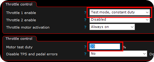
Enable the Test mode, constant duty function, and enter a motor test duty value to be outputted on the motor outputs.
Note: use with caution since this function can brake your throttle body.
When using this feature, please always go back to "0" values before entering a new test duty.
The below steps requires all calibration to be correctly made.
1.Enter a positive duty and watch the throttle to open, if it closes, shift motor+ and motor- outputs in output config. Find the duty number that opens the throttle to 100%.
2.Enter a negative duty and watch the throttle to close. Find the duty number that closes the throttle to 0%.
3.Enter "0" as motor duty, this is the throttle rest position and will vary depending on throttle used.
4.Fill the feed forward table with the data you got from the above testings.
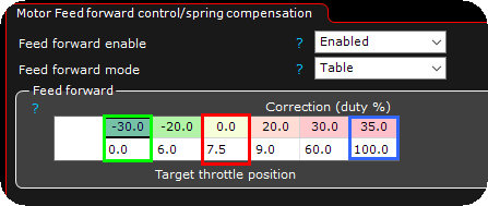
Example of a populated motor feed forward table (to get closer to correct position before starting the PID regulator).
Green: The required duty to fully closing the throttle.
Red: Throttle rest position.
Blue: The required duty to fully open the throttle.
E-Throttle tuning
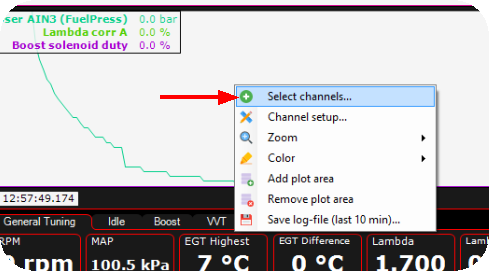
First, select the channels to be showed in live-logger.
1.Main throttle position(s)
2.Target throttle position(s)

All throttle control settings needs to be changed to make the throttle position as close to the target throttle position as possible, under all circumstances to make a perfect control of the E-Throttle body. This is not easy and it will require a lot of time to actually do it.
E-Throttle idle tuning
Note: Idle control with E-Throttle is easy, if the actual PID regulator settings for the E-Throttle is correctly made, make sure the control of the E-Throttle is very accurate even before trying to do the idle control with the E-Throttle.

In E-Throttle --> Throttle control, there is an Idle control settings with max and min values of the actual throttle positions that the idle control functions can use.
Preferable set the min value right below the actual throttle opening position value when you are satisfied with engine rpm during idle on warm engine.
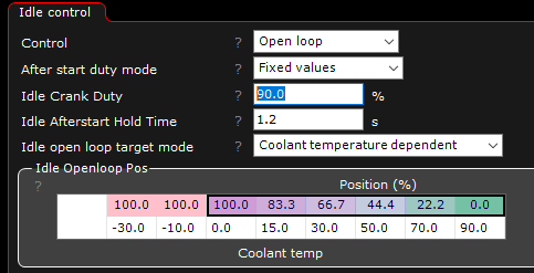
The actual idle control (found in Outputs --> Idle control) takes the idle control min and max values from the throttle control pages.
For an example, an idle control duty of 0% means 2% throttle opening. An idle control duty of 100% means 10% actual throttle opening.
Note: Always adjust the open loop duty tables before even try to enter the closed loop mode, since when closed loop functions are deactivated, the open loop tables are used (if for example disable over speed is used in closed loop mode).
Built-in error checking functions
Error checking for both pedals and throttles are built-in, do not disable them unless you are 100% sure what you are doing.

Throttle error checking enable/disable.

Throttle position allowed error, check RealTime Data value: Throttle position sensor error.
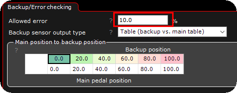
Pedal position allowed error, check RealTime Data value: Pedal position sensor error.